Content
- 1 What Are Boiler Finned Tubes and How Do They Work?
- 2 Key Types of Finned Tubes Used in Boiler Applications
- 3 Materials: Matching Metallurgy to Operating Conditions
- 4 Fin Geometry Parameters and Their Effect on Performance
- 5 Manufacturing Methods: How Fins Are Attached
- 6 Applications Across Boiler Systems
- 7 Quality Standards and Inspection Requirements
- 8 Maintenance, Fouling, and Service Life Considerations
What Are Boiler Finned Tubes and How Do They Work?
Boiler finned tubes are heat transfer components equipped with extended surface fins along their outer walls, designed to dramatically increase the rate of heat exchange between hot flue gases and the fluid flowing inside the tube. By expanding the effective contact area — sometimes by a factor of 5 to 10 times compared to a plain tube — finned tubes allow boilers to extract more energy from combustion gases before they exit the stack, directly improving thermal efficiency.
The operating principle is straightforward: hot gases pass over the finned surface, transferring heat both to the fins and to the base tube wall. The fins conduct that heat inward to the tube, where it is absorbed by water, steam, or another heat-transfer medium. The geometry, material, and fin density are all engineered to balance heat transfer performance against pressure drop and fouling resistance.
Key Types of Finned Tubes Used in Boiler Applications
Different boiler designs and operating conditions call for different fin configurations. The most commonly specified types include:
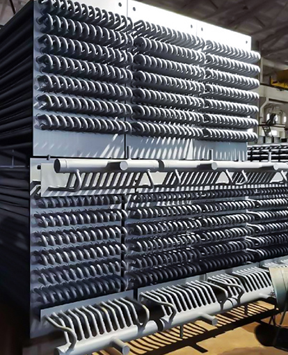
- Helical (Spiral) Finned Tubes — A continuous strip fin wound helically around the base tube. Widely used in economizers and air preheaters due to their uniform fin spacing and structural integrity under thermal cycling.
- Longitudinal Finned Tubes — Fins running parallel to the tube axis, preferred where the gas flow is parallel to the tube length or where drainage of condensate is critical.
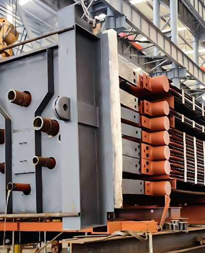
- Studded Tubes — Individual studs welded onto the tube surface, used in high-temperature, high-ash environments such as biomass and waste-heat boilers where continuous fins would accumulate ash and plug gas passages.
- H-Type (HH) Finned Tubes — Square or rectangular fin panels welded to the tube in pairs, delivering a large surface area with relatively wide gas lanes to resist fouling in coal-fired utility boilers.
- Extruded Finned Tubes — Produced by mechanically deforming an outer sleeve into fins around the base tube, achieving excellent metallurgical contact and used where corrosion resistance is paramount.
Selecting the correct type depends on gas-side temperature, fouling tendency of the fuel, tube-side pressure, and the required approach temperature between gas outlet and feed-water inlet.
Materials: Matching Metallurgy to Operating Conditions
Material selection is one of the most consequential decisions in finned tube specification. The base tube and fin must withstand sustained exposure to high temperatures, corrosive flue-gas constituents (SO₂, HCl, NOₓ), and pressure cycling — often simultaneously.
| Material | Max Continuous Temp. | Typical Application |
|---|---|---|
| Carbon Steel (SA-179 / SA-192) | ~450 °C | Economizers, low-temperature air preheaters |
| Alloy Steel (T11, T22) | ~580 °C | Superheater and reheater zones |
| Stainless Steel (304, 316, 321) | ~700 °C | Corrosive gas streams, waste incineration boilers |
| TP347H / Super 304H | ~750 °C | Ultra-supercritical (USC) boilers |
| Nickel Alloys (Inconel 625, 825) | >800 °C | High-chlorine or high-sulfur environments |
Fin material does not always need to match the base tube. A common pairing in economizer service is a carbon steel base tube with solid stainless steel fins, which resists dew-point corrosion on the outer surface while keeping raw material costs controlled.
Fin Geometry Parameters and Their Effect on Performance
Thermal engineers optimize four primary geometric variables when specifying finned tubes for a boiler heat recovery section:
- Fin Height (h) — Taller fins add more surface area but increase gas-side pressure drop and reduce fin efficiency. Heights typically range from 6 mm to 25 mm in utility boiler applications.
- Fin Thickness (t) — Thicker fins conduct heat more effectively and resist erosion but add weight and cost. Values between 2 mm and 4 mm are common for welded carbon steel fins.
- Fin Pitch (p) — Closer pitch (more fins per meter) increases total surface area but narrows the gas lane, accelerating fouling. For high-ash fuels, pitches of 80–120 fins/m are typical; clean gas streams may use 200–300 fins/m.
- Fin Efficiency (η) — A calculated dimensionless ratio comparing actual heat transferred by the fin to what a perfect, isothermal fin would transfer. Values above 0.85 are generally targeted to ensure the extended surface is adding real benefit.
Serrated (notched) helical fins are increasingly specified in HRSG (Heat Recovery Steam Generator) applications because the interrupted fin surface disrupts the gas boundary layer, improving the convective heat transfer coefficient by 10–20% relative to solid fins of identical geometry, without a proportionate increase in pressure drop.
Manufacturing Methods: How Fins Are Attached
The bond between fin and tube is critical. Poor thermal contact at the joint — caused by gaps, oxide layers, or inadequate fusion — creates an interfacial resistance that can eliminate most of the efficiency gain the fin was added to provide. The main attachment methods are:
- High-Frequency Resistance Welding (HFW/HF-ERW) — The industry standard for helical fins. A high-frequency electrical current concentrates at the fin-to-tube contact point, creating a forge weld without filler metal. Produces a continuous, metallurgically bonded joint with contact resistance approaching zero.
- Submerged Arc Welding (SAW) — Used for H-type and other thick, discrete fins. Provides robust mechanical strength and is well-suited to heavy-wall tubes in high-pressure applications.
- Brazing — Applied to aluminum and copper finned tubes used in low-temperature, low-pressure boiler auxiliaries such as air preheaters and oil coolers.
- Mechanical Tension Winding (L-foot or G-type) — The fin strip is formed with a foot that wraps around the tube under tension. Lower cost but susceptible to contact resistance growth after repeated thermal cycling; generally limited to non-critical, below-250 °C services.
Applications Across Boiler Systems
Finned tubes are used throughout the boiler island, each location presenting distinct thermal and mechanical challenges:
- Economizers — Recover heat from flue gas to preheat boiler feed water, reducing fuel consumption. This is the highest-volume application for carbon steel helical finned tubes globally.
- Superheaters and Reheaters — Operate at the highest tube temperatures in the boiler. Finned tubes here are typically alloy steel or austenitic stainless steel with wide-pitch fins to manage gas-side temperatures and minimize creep risk.
- HRSGs (Heat Recovery Steam Generators) — Combined-cycle power plants rely almost entirely on finned tube bundles to extract heat from gas turbine exhaust. HRSG modules are the single largest application by tube count for serrated finned tubes.
- Waste Heat Boilers (WHBs) — Installed downstream of industrial processes (cement kilns, glass furnaces, chemical reactors) to convert waste thermal energy into usable steam or electricity.
- Biomass and Waste-to-Energy Boilers — High-chlorine, high-alkali flue gases demand corrosion-resistant alloys and wider fin pitches or studded geometries to prevent fouling and corrosion.
Quality Standards and Inspection Requirements
Boiler finned tubes destined for pressure service must conform to recognized codes and be subject to rigorous quality assurance. Key reference standards include:
- ASME Section I — Rules for construction of power boilers, including material qualification for pressure-containing components.
- ASTM A-179 / A-192 / A-213 — Base tube material specifications for seamless carbon steel and alloy steel boiler tubes.
- EN 10216-2 — European equivalent standard for seamless steel tubes for pressure purposes at elevated temperatures.
- Hydrostatic Testing — Each tube is pressure-tested to verify weld and tube integrity before shipment.
- Eddy Current Testing (ECT) — Non-destructive examination to detect cracks, weld voids, and wall-thickness anomalies, particularly in the fin weld zone.
Third-party inspection by bodies such as TÜV, Bureau Veritas, or Lloyd's Register is routinely required on major power plant and HRSG contracts, covering mill certificates, dimensional checks, weld quality, and hydro-test witnessed hold points.
Maintenance, Fouling, and Service Life Considerations
Even the best-designed finned tubes require a maintenance strategy. Fouling — the accumulation of ash, soot, or mineral scale on fin surfaces — increases gas-side thermal resistance and raises flue-gas outlet temperature, both of which cut boiler efficiency. A 1 mm ash layer on finned tube surfaces can reduce heat transfer effectiveness by 8–15% in typical utility boiler service.
Effective fouling management strategies include:
- Soot blowing with steam or compressed air during operation
- Acoustic cleaning (sound horns) for dry, light deposits
- Water washing during planned shutdowns for heavy mineral scale
- Optimizing fin pitch at the design stage to match predicted ash loading
With proper material selection and preventive maintenance, welded helical finned tubes in clean gas service routinely achieve service lives exceeding 20 years. In aggressive environments such as municipal solid waste combustion, planned replacement cycles of 8–12 years may be more realistic.