Content
- 1 The Core Principle: Heat Exchange Between Flue Gas and Feedwater
- 2 Key Components That Make Up a Boiler Economizer
- 3 How Efficiency Gains Are Calculated
- 4 Types of Boiler Economizers and Their Specific Applications
- 5 The Risk of Low-Temperature Corrosion and How to Manage It
- 6 Integration into HRSG Systems
- 7 What to Look For When Selecting a Boiler Economizer
- 8 Maintenance Practices That Preserve Long-Term Performance
A boiler economizer is one of the most cost-effective components you can add to any industrial boiler system. In simple terms, it recovers heat from flue gas that would otherwise be wasted up the stack and uses that recovered energy to preheat the feedwater before it enters the boiler drum. The result is a measurable reduction in fuel consumption and a meaningful improvement in overall thermal efficiency — often in the range of 5% to 15% depending on system conditions and flue gas temperature.
For facility managers and plant engineers who run boilers around the clock, that efficiency gain translates directly into lower operating costs and reduced emissions. Understanding how the economizer actually works — and how to select or maintain one correctly — is therefore a practical concern, not just a technical one.
The Core Principle: Heat Exchange Between Flue Gas and Feedwater
The economizer is positioned in the boiler's exhaust gas path — typically in the rear pass or tail flue section — after the main heat exchange surfaces such as the superheater and evaporator. By this point, the flue gas has already given up its high-temperature heat to generate steam, but it still carries a significant amount of thermal energy. In most industrial boilers, flue gas at this stage ranges from 200°C to 400°C. Without an economizer, that heat exits through the stack and is lost entirely.
The economizer intercepts this flow. Feedwater from the feed pump enters the economizer tubes at a relatively low temperature — commonly between 30°C and 80°C — and flows through a serpentine or coiled tube arrangement while hot flue gas passes over or across the tube bundle on the shell side. Heat is transferred from the gas to the water through the tube walls, raising the feedwater temperature before it enters the steam drum or evaporator section.
This is a counterflow heat exchange process: flue gas and feedwater typically travel in opposite directions, which maximizes the temperature difference across the heat transfer surfaces and improves efficiency. A well-designed economizer can raise feedwater temperature by 20°C to 60°C in a single pass, depending on the surface area, tube geometry, and gas velocity.
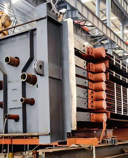
Key Components That Make Up a Boiler Economizer
Understanding what an economizer consists of helps clarify why design choices matter so much in terms of performance and service life.
- Tube bundle: The core heat transfer element. Tubes are typically made from carbon steel (e.g., SA210C) for standard applications or alloy steel grades like T91 or 12Cr1MoVG for higher-temperature or corrosive environments. The tube outer diameter, wall thickness, and layout pitch all affect heat transfer coefficient and pressure drop.
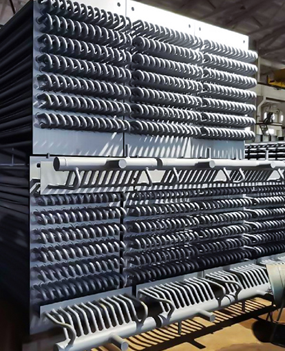
- Finned tubes (where applicable): Many economizers use finned tubes — either spiral or H-type — to increase the external surface area exposed to flue gas. A finned tube can increase effective heat transfer area by a factor of 3 to 6 compared to a bare tube of the same length, significantly reducing the physical footprint of the unit.
- Headers and manifolds: Inlet and outlet headers collect and distribute feedwater evenly across the tube rows. Proper header design ensures uniform flow distribution, which prevents localized overheating or flow stagnation.
- Casing and bypass dampers: The outer casing contains the tube bundle within the flue gas stream. Some designs include bypass dampers that allow operators to divert flue gas around the economizer during low-load conditions, preventing condensation issues.
- Sootblowers or cleaning systems: In coal-fired or biomass systems where flue gas carries particulate matter, periodic tube cleaning is necessary to maintain heat transfer performance and prevent ash bridging.
How Efficiency Gains Are Calculated
A widely used rule of thumb in boiler engineering is that every 6°C drop in flue gas exit temperature corresponds to approximately 1% improvement in boiler thermal efficiency. This figure varies with fuel type and system configuration, but it gives a useful order-of-magnitude sense of what an economizer delivers.
Consider a natural gas boiler operating at 10 MW input with a flue gas exit temperature of 350°C. Installing an economizer that reduces the exit temperature to 180°C — a reduction of 170°C — would theoretically improve efficiency by around 28 percentage points of that range, or roughly 4–5% absolute efficiency gain depending on the specific setup. Over a year of continuous operation, that translates to substantial fuel savings and a correspondingly significant reduction in CO₂, NOₓ, and particulate emissions.
The improved feedwater temperature also reduces thermal stress on the boiler drum by narrowing the temperature differential between incoming water and the hot drum metal — a benefit for both boiler longevity and operational stability.
Types of Boiler Economizers and Their Specific Applications
Not all economizers are alike. The right design depends heavily on the fuel type, flue gas composition, temperature range, and dust loading. Below is a comparison of common types we manufacture:
| Economizer Type | Typical Flue Gas Temperature | Primary Application | Key Design Feature |
|---|---|---|---|
| Boiler Tail Flue Gas Economizer | 120–400°C | Coal-fired, gas-fired, biomass boilers | High surface area finned tubes, low-temperature corrosion protection |
| Industrial Kiln Flue Gas Economizer | 400–600°C | Ceramic kilns, glass furnaces, metallurgical kilns | Dust-resistant tube spacing, wear-resistant materials |
| Process Equipment Flue Gas Economizer | 250–400°C | Refineries, petrochemical heaters, synthesis reactors | Corrosion-resistant alloys, sealed design for hazardous media |
| HRSG Economizer Module | 150–350°C | Gas turbine exhaust, combined cycle power plants | Modular assembly, horizontal or vertical gas flow configuration |
The choice between bare tube and finned tube construction is particularly important. For clean gas applications such as natural gas or light oil, spiral finned tubes are standard because they maximize surface area without fouling concerns. For dusty flue gas from coal combustion or kiln exhaust, H-type finned tubes with wider fin spacing and flat fin geometry are preferred — they allow particulate to pass through more freely and are easier to clean.
The Risk of Low-Temperature Corrosion and How to Manage It
One of the most important design constraints for a boiler economizer is the acid dew point of the flue gas. When sulfur-containing fuels — coal, heavy fuel oil, process gas with H₂S — are burned, sulfur trioxide (SO₃) forms in the combustion zone. In the flue gas stream, SO₃ reacts with water vapor to form sulfuric acid vapor. If the tube surface temperature falls below the acid dew point (typically 120°C to 160°C for sulfur-bearing fuels), sulfuric acid condenses on the tube surface and causes rapid corrosion.
This is why economizer outlet flue gas temperature is not simply driven to the lowest possible value — there is a practical floor determined by corrosion risk. For fuel oil or coal-fired systems, flue gas exit temperature is typically maintained above 140–160°C to provide a safety margin above the acid dew point.
Strategies for Managing Low-Temperature Corrosion
- Use of corrosion-resistant tube materials such as ND steel (09CrCuSb), which is specifically developed for this environment and significantly outperforms standard carbon steel in sulfuric acid condensate
- Maintaining minimum feedwater temperature at the economizer inlet, typically above 60°C, to keep tube metal temperature above the dew point
- Installing a low-temperature economizer as a secondary stage downstream, specifically designed with corrosion-resistant materials to recover additional heat below the conventional dew point limit
- Monitoring flue gas sulfur content and adjusting bypass operation during fuel quality changes
Integration into HRSG Systems
In heat recovery steam generators (HRSG), the economizer is not a standalone add-on but an integral part of the pressure-part module stack. A typical HRSG in a combined cycle power plant will have multiple pressure levels — high pressure (HP), intermediate pressure (IP), and low pressure (LP) — each with its own evaporator and economizer section. The gas turbine exhaust, typically entering at 500°C to 620°C, cascades through superheaters, evaporators, and economizers at each pressure level in sequence.
The economizer sections in this arrangement serve the same fundamental role as in a conventional boiler — preheating feedwater using residual flue gas heat — but must be engineered for the specific temperature windows, flow rates, and steam generation requirements of the HRSG cycle. Module-to-module alignment, thermal expansion management, and bypass provisions all become critical engineering factors at this scale.
For projects at this scale, we supply fully engineered HRSG modules including economizer sections, with materials and configurations specified to each pressure level and gas temperature profile.
What to Look For When Selecting a Boiler Economizer
If you are evaluating an economizer for a new or existing boiler system, the following parameters should be clearly defined before engaging a manufacturer:
- Flue gas flow rate and temperature range — both design point and minimum/maximum operating conditions
- Feedwater inlet temperature and target outlet temperature — determines required heat transfer duty
- Fuel type and sulfur content — determines corrosion risk and material selection
- Flue gas dust loading — affects fin type selection and cleaning system requirements
- Available space and installation orientation — vertical vs. horizontal gas flow affects module layout
- Applicable codes and pressure vessel standards — ASME, EN, or local national standards depending on project location
- Maintenance accessibility — tube cleaning access, inspection ports, and header drain provisions
A well-specified economizer matched to these parameters will deliver its rated efficiency improvement consistently over a 15–20 year service life with minimal maintenance. An undersized or incorrectly specified unit may fail to reach design performance or suffer premature tube failures — erasing the projected payback entirely.
We offer a full range of industrial boiler economizers designed and manufactured to customer-specific process conditions, with configurations for boiler tail flue gas recovery, industrial kiln exhaust, and petrochemical process applications. All units are produced under ASME-S and ISO-certified quality systems.
Maintenance Practices That Preserve Long-Term Performance
Even a well-designed economizer will degrade in performance if maintenance is neglected. The two primary degradation mechanisms are external fouling (ash and soot deposition on tube surfaces) and internal scaling or corrosion (from poor feedwater quality or acid condensate).
External Fouling
A 1 mm soot layer on a tube surface can reduce its heat transfer coefficient by 10–20%. In coal-fired and biomass systems, scheduled sootblowing during operation and water washing during outages are standard practice. The frequency depends on fuel ash content — high-ash coals may require daily blowing cycles, while low-dust gas-fired systems may need only annual cleaning.
Internal Scaling and Water Quality
Calcium and magnesium scale inside economizer tubes insulates the inner wall and progressively raises tube metal temperatures. A 0.5 mm scale layer can increase tube wall temperature by 30–50°C, increasing corrosion risk and eventually leading to tube failure. Maintaining proper boiler water treatment — including hardness control, deaeration, and pH management — is as important as any mechanical maintenance task.
Periodic inspection using eddy current testing or ultrasonic wall thickness measurement allows early detection of wall thinning before it becomes a failure risk. Establishing a baseline measurement at commissioning and tracking changes over successive outages gives operators the data needed to plan tube replacement proactively rather than reactively.