English
  Français
  Español

Content
- 1 The Primary Function of Boiler Finned Tubes
- 2 Understanding Heat Transfer Mechanics
- 3 Material Selection for Harsh Operating Environments
- 4 Core Manufacturing Processes and Attachment Methods
- 5 Common Failure Mechanisms and Root Cause Analysis
- 6 Effective Cleaning Strategies to Maintain Performance
- 7 Optimizing Geometry for Specific Fuel Types
- 8 Inspection Protocols During Shutdowns
The Primary Function of Boiler Finned Tubes
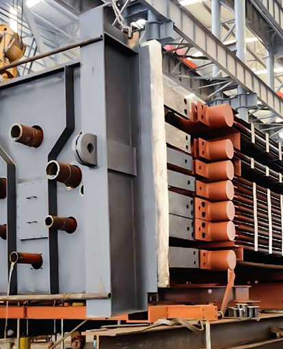
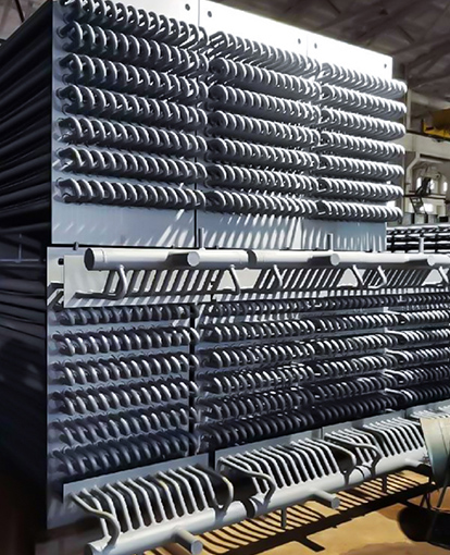
The central purpose of a boiler finned tube is to increase the external surface area without proportionally increasing the tube's overall diameter or weight. By attaching fins to the base tube, the heat exchanger can transfer significantly more thermal energy from the hot flue gas to the water or steam inside the tube. This process directly improves the thermal efficiency of the boiler, enabling a more compact design and reducing fuel consumption over the operational life of the equipment.
In practical terms, a finned tube economizer can reduce exhaust gas temperatures by up to 40 degrees Celsius compared to a bare tube design in the same footprint. This recovery of waste heat directly translates into a fuel savings potential of approximately 1 percent for every 20 degrees Celsius reduction in stack temperature, making the technology a critical component in modern energy management.
Understanding Heat Transfer Mechanics
The effectiveness of these components rests on the principle that heat transfer rate is a function of surface area, temperature difference, and the heat transfer coefficient. On the gas side of a boiler, the dominant resistance to heat flow usually occurs. Fins work by extending the surface into the gas stream, overcoming the inherently low convection coefficient of gases.
| Characteristic | Bare Tube | Finned Tube |
|---|---|---|
| External Surface Area per Meter | ~0.1 m² | Up to 1.5 m² |
| Heat Transfer Rate | Base reference | 300% to 500% higher |
| Required Tube Rows | High | Reduced by up to 70% |
| Gas-Side Pressure Drop | Lower | Higher (requires careful design) |
However, the efficiency of a fin is not uniform. A parameter known as fin efficiency dictates that the temperature drops along the fin’s height as heat dissipates. The material choice becomes critical here because a fin material with higher thermal conductivity, such as aluminum or copper, will maintain a higher average temperature across its surface compared to carbon steel, resulting in more effective heat rejection.
Material Selection for Harsh Operating Environments
Selecting the correct metallurgy prevents mechanical failure and ensures operational longevity. The choice is dictated by the flue gas temperature and the corrosive potential of the fuel being burned. Incorrect matching is a primary cause of premature failure.
Carbon Steel Fins
These are cost-effective and suitable for clean gas streams with temperatures generally below 400 degrees Celsius. The limitation is their susceptibility to oxidation and acidic dew point corrosion. If sulfur is present in the fuel, the metal temperature must stay above the acid dew point, typically around 120 to 140 degrees Celsius, to avoid rapid acidic attack.
Stainless Steel Fins
For higher temperatures up to 650 degrees Celsius or highly corrosive environments such as waste-to-energy plants, austenitic stainless steel grades are required. The chromium content forms a passive oxide layer, resisting attack. While the initial capital cost is significantly higher, the lifecycle cost is often lower due to extended service intervals and reduced unexpected downtime.
Aluminum Fins
Used extensively in air-cooled condensers, aluminum offers excellent thermal conductivity and is highly resistant to atmospheric corrosion. However, its melting point limits use to very low temperature boiler exhaust applications, specifically below 200 degrees Celsius.
Core Manufacturing Processes and Attachment Methods
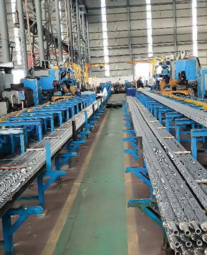
The bond between the fin and the tube is the most structurally and thermally critical point. A poor bond introduces an air gap which acts as an insulator, severely degrading performance. Several distinct processes exist to optimize this bond for different temperatures and stress conditions.
- High-Frequency Resistance Welding: This process produces a continuous, helical fin. It results in a forged-like, solid-state bond between the fin and tube without the need for filler metal. This is the standard for power generation boilers, providing integrity at tube metal temperatures up to 600 degrees Celsius.
- Extruded Fin Tubes: A thick aluminum outer sleeve is placed over a core tube and extruded under high pressure, creating high-integrity fins. The lack of a weld joint eliminates galvanic corrosion risk at the base. This design is optimal for offshore heat exchangers exposed to saline atmospheres.
- Embedded Fin Tubes: The fin is mechanically inserted into a helical groove cut into the tube wall and secured by rolling back the displaced metal. The mechanical lock provides excellent thermal cycling tolerance, preventing bond loosening caused by expansion and contraction during boiler start-ups and shutdowns.
Common Failure Mechanisms and Root Cause Analysis
Recognizing failure patterns enables maintenance teams to address root causes rather than just replacing components. Three primary mechanisms are observed in the field:
- Fly Ash Erosion: A cutting action occurs when abrasive ash particles impact the leading edge of the fins. The wear rate is proportional to the gas velocity cubed. Engineers often specify a gas-side velocity limit of 15 to 20 meters per second depending on ash loading to minimize this issue. Erosion shields or U-bends can be installed on the first rows of tube banks as sacrificial barriers.
- Dew Point Corrosion: This occurs when the metal surface temperature drops below the condensation temperature of acidic gases, particularly sulfuric acid. The corrosion is typically localized at the cold end of the system. A practical predictive measure is to regularly track the minimum tube metal temperature relative to the calculated acid dew point, rather than just monitoring bulk flue gas exit temperatures.
- Fin Loosening: Cyclic thermal stress can cause the interface between a non-welded fin and the tube to relax. Once loosening starts, the thermal contact resistance increases, causing the tube metal to overheat while the fin cools down uselessly. Tapping inspections during shutdowns can audibly identify loose fins through a flat, rattling sound rather than a clean, ringing tone.
Effective Cleaning Strategies to Maintain Performance
Fouling by soot, ash, or scale deposits negates the surface-area advantage that justifies the use of finned tubes. A deposit layer of just 0.5 millimeters can reduce heat transfer efficiency by 10 to 20 percent. A disciplined cleaning regimen is non-negotiable.
Sootblowers utilizing high-pressure steam remain the most common online cleaning method. However, aggressive operation can cause erosion. Sonic horns, which use low-frequency sound waves to fluidize and lift deposits, are a complementary technology that reduces the mechanical fatigue on tube bundles. For offline cleaning, high-pressure water washing must be strictly controlled. If the water pressure exceeds the fin’s structural stiffness, the fins can bed over or "lay down," permanently blocking the gas path and choking the flow.
Optimizing Geometry for Specific Fuel Types
The geometry of the fin must match the dirtiness of the fuel. There is an inverse relationship between surface density and cleanability. For units firing high-ash coals or biomass, a wider fin pitch is essential to prevent plugging.
A practical guideline is that for fuels with ash content exceeding 15 percent, the clear gap between fin tips should be no less than 6 to 8 millimeters. Conversely, for clean-burning natural gas combined cycle heat recovery steam generators, a tight fin density of up to 275 fins per meter can be safely specified. This maximizes the heat absorption in a very compact space without risking blockage, as the gas contains virtually no particulate matter.
Inspection Protocols During Shutdowns
Visual inspection during boiler shutdowns provides irreplaceable data on unit health. The first step is a photographic survey of the tube banks. Comparing images from successive outages helps quantify the rate of erosion damage. Thickness measurements using ultrasonic testing should be taken at the 12 o'clock and 3 o'clock positions of the base tube, as these locations typically experience the highest erosive wear from gas flow impingement.
Additionally, a fin profile gauge can be used to check for bending. Bending beyond a 10-degree angle from the vertical creates turbulence between adjacent fins, accelerating localized erosion on the neighboring tubes. Documenting the pattern of deformation helps differentiate between a design flaw causing vibration and an operational upset causing thermal shock.