English
  Français
  Español

Content
- 1 How Finned Tubes Reshape Heat Transfer in Boilers
- 2 Selecting the Right Fin Type for Boiler Conditions
- 3 Material Strategies Against Low-Temperature Corrosion
- 4 Optimizing Geometry and Flow for Peak Performance
- 5 Operational Maintenance That Protects the Investment
- 6 The Road Ahead: Material and Structural Evolution
Finned tubes provide a direct and measurable path to higher boiler efficiency by enlarging the effective heat transfer surface on the flue gas side. When retrofitted into an economizer or air preheater, a well-engineered finned tube bank can lower the stack gas temperature by 15 to 25 degrees Celsius, translating into a fuel saving of 2% to 5% and a rapid payback period that rarely exceeds 18 months in continuous operation. This efficiency gain is achieved without increasing the boiler footprint, making finned tubes the preferred solution for upgrading low-temperature heat recovery surfaces.
How Finned Tubes Reshape Heat Transfer in Boilers
In bare tube economizers, the dominant thermal resistance lies on the flue gas side because gas convective heat transfer coefficients are inherently low, typically in the range of 20 to 60 W/m²·K. By attaching fins to the outer surface of the tube, the total external area can be multiplied by a finning ratio of 5 to 12, effectively reducing the gas-side resistance proportionally. The overall heat transfer coefficient can rise by 40% to 80% compared with a smooth tube bundle of the same base tube diameter and flow cross-section.
This transformation is particularly valuable in boilers fired with natural gas, biomass, or coal where the flue gas temperature after the primary superheater still holds substantial recoverable energy. Instead of increasing the number of tube rows, designers add fins to achieve the required duty with fewer tubes, which also reduces the gas-side pressure drop and fan power consumption.
Selecting the Right Fin Type for Boiler Conditions
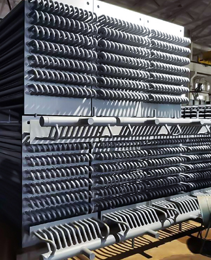
The choice between spiral fin tubes and H-shaped fin tubes is primarily governed by the cleanliness of the flue gas and the temperature window. The table below summarizes the practical differences.
| Fin Type | Typical Fin Pitch | Ash Handling | Best Application |
|---|---|---|---|
| Spiral solid fin | 4–8 mm | Moderate fouling risk | Gas and light oil boilers |
| H-shaped fin (double fin) | 8–18 mm | Excellent, self-cleaning channels | Coal, biomass, and high-ash fuels |
| Longitudinal fin | Continuous | Low gas-side pressure drop | Clean gas streams, compact preheaters |
H-shaped fins are especially effective in dirty gas environments because the vertical fin plates create a straight channel that allows fly ash to pass through without bridging. Field measurements on a 75 t/h coal-fired boiler showed that H-fin economizers maintained a heat transfer coefficient within 8% of the clean value after 4,000 operating hours, while spiral fin bundles in the same flue gas experienced a 25% degradation due to ash buildup.
Material Strategies Against Low-Temperature Corrosion
The metal temperature of the cold end of a finned tube must remain above the acid dew point of the flue gas to avoid sulfuric acid condensation. When the tube wall temperature dips below 120 to 140 degrees Celsius, depending on fuel sulfur content, rapid corrosion attack can occur within weeks.
To counter this, materials are matched to the expected operating window:
- Carbon steel with a minimum wall temperature above 115°C for natural gas firing.
- Corten or low-alloy steel (09CrCuSb) for moderate sulfur fuels, offering a 2 to 3 times longer life in sulfate-rich condensate.
- Stainless steel grades such as 316L or duplex stainless when the feedwater inlet temperature cannot be raised and the tube wall remains persistently near the dew point.
- New corrosion-resistant alloys containing chromium and molybdenum, which form a stable passive layer and withstand pH values as low as 2.5 during cold start-ups.
Where acid condensation cannot be avoided entirely, an increasing number of operators specify an all-welded fin strip connection that eliminates crevice corrosion at the fin root, effectively extending the service life by 30% to 50% compared with mechanically bonded fins.
Optimizing Geometry and Flow for Peak Performance
Fin height, thickness, and spacing must be tuned to the gas velocity and dust load. For an economizer handling flue gas with a dust content below 5 g/Nm³, a fin height of 12 to 16 mm and a pitch of 5 to 7 mm provide an ideal balance between area extension and pressure loss. In contrast, for biomass boilers with higher ash loads, the pitch is widened to 12 to 16 mm to accommodate on-line soot blowing and reduce erosion.
Tube-side fluid velocity is equally critical. In an economizer tube, the water mass velocity should be kept above 1.2 m/s to suppress scale deposition and ensure adequate film heat transfer. A practical design approach uses these steps:
- Define the required duty from the flue gas inlet and outlet temperatures.
- Select a preliminary fin geometry and compute the extended surface area.
- Check the gas-side Reynolds number to stay above 5,000, ensuring turbulent flow and high fin efficiency.
- Verify that the metal temperature at the cold end exceeds the acid dew point by at least 15°C under part-load conditions.
- Adjust row depth and pitch iteratively until the gas-side pressure drop is below 250 Pa for natural-draft boilers.
Operational Maintenance That Protects the Investment
Even the best finned tube design will underperform if fouling and corrosion are allowed to progress unchecked. A structured maintenance routine makes a measurable difference:
- Inspect fin integrity during each boiler shutdown, recording any fin tip erosion that exceeds 0.5 mm loss.
- Operate steam or acoustic soot blowers at the recommended frequency; data from a 50 MW cogeneration plant showed that reducing soot blowing intervals from 8 hours to 4 hours cut ash-related heat transfer loss from 12% to 3%.
- Monitor exit gas temperature trends. A gradual rise of 5°C or more over a six-month period often signals fin fouling before visible buildup appears.
- Conduct water-side chemical cleaning when the pressure drop across the tube bundle increases by 20% above the clean condition, avoiding pitting under deposits.
The Road Ahead: Material and Structural Evolution
Future boiler designs demand finned tubes that deliver lower resistance and higher corrosion tolerance. Laser-welded fin profiles with a tapered cross-section reduce wake formation and can trim the gas-side pressure drop by 10% to 15% while maintaining the same heat transfer. Advanced ferritic alloys containing 12% chromium are now being tested in waste-to-energy boilers, with early field data showing negligible wall thickness loss after two years of exposure to high-chlorine flue gas.
Digital twins of finned tube banks, fed with real-time temperature and pressure data, now allow operators to predict remaining life and schedule replacements precisely. This condition-based approach is expected to reduce unplanned outages related to cold-end corrosion by over 40%.