Content
- 1 Why Surface Area Is the Limiting Factor
- 2 Three Fin Types That Do the Heavy Lifting
- 3 Where Finned Tubes Appear in a Power Plant
- 4 Geometry Choices That Engineers Optimize
- 5 Fouling: The Efficiency Leak No One Ignores
- 6 Material Selection in High-Temperature Service
- 7 The Net Effect on Power Plant Economics
A plain boiler tube loses a measurable share of combustion energy straight out the stack. Add fins to the outer wall, and that same tube can exchange 5 to 10 times more heat with passing flue gas — without increasing the boiler's footprint. That single geometry change sits at the heart of modern power plant efficiency.
Why Surface Area Is the Limiting Factor
Heat transfer between a hot gas stream and a tube wall is governed by a straightforward constraint: the larger the contact surface, the faster energy moves across it. In a conventional smooth-bore tube, that surface is fixed by diameter and length. Boiler finned tubes break that constraint by attaching extended metal surfaces — fins — to the tube's outer wall, giving flue gas a much larger area to surrender its heat before exiting the system.
The physics works in two parallel paths. Hot gas transfers heat convectively to the fin surface; the fin conducts that energy inward to the base tube; and the tube wall transfers it to the feedwater or steam inside. Every degree of gas temperature recovered before the stack is fuel that doesn't need to be burned on the next cycle.
Three Fin Types That Do the Heavy Lifting
Not every power plant runs on the same fuel or at the same temperature, which is why multiple fin configurations exist in commercial service.
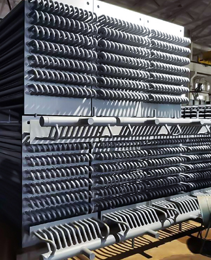
Helical (Spiral) Finned Tubes are the workhorse of gas-fired and combined-cycle plants. A continuous fin strip is wound around the base tube by high-frequency resistance welding, producing a metallurgically bonded joint with near-zero contact resistance. When the fin surface is serrated rather than solid, the interrupted geometry disrupts the gas boundary layer and improves the convective heat transfer coefficient by 10–20% relative to plain helical fins — a meaningful gain in HRSG modules that process millions of cubic meters of turbine exhaust daily.
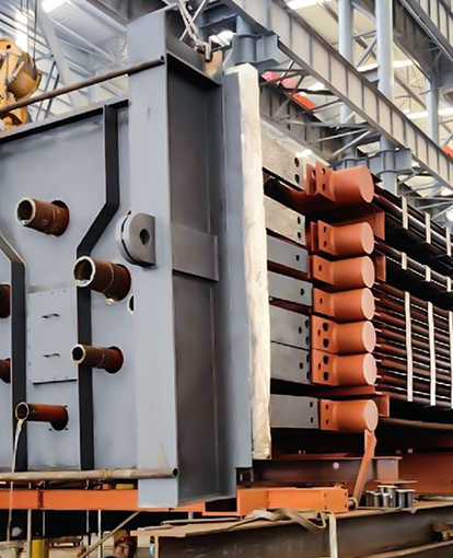
H-Type Finned Tubes use rectangular fin panels welded in pairs, creating wide gas lanes between fins. This geometry resists ash bridging in coal-fired utility boilers and is specified wherever fouling is a primary design constraint. The wider pitch trades some surface area for better soot-blowing access and longer cleaning intervals.
Studded Tubes replace continuous fins with individual welded pins. Used in biomass and waste-to-energy boilers where high chlorine or alkali content in the flue gas would accelerate corrosion of exposed fin edges, studs present less metal to the aggressive gas stream while still expanding the effective surface area.
Where Finned Tubes Appear in a Power Plant
Finned tubes are not confined to one component — they appear across the entire heat recovery chain.
In boiler economizers, carbon steel helical finned tubes absorb residual flue gas heat and transfer it to incoming feedwater, typically cutting fuel consumption by 2–5% per installation. In superheaters and reheaters, alloy steel or stainless fins operate at temperatures above 550 °C, squeezing additional enthalpy into the steam before it hits the turbine. In Heat Recovery Steam Generators (HRSGs) — the defining component of combined-cycle power — the entire boiler is essentially a stack of finned tube bundles arranged in series to extract maximum energy from gas turbine exhaust at progressively lower temperature levels.
Geometry Choices That Engineers Optimize
Four variables control how much a finned tube actually delivers in service:
- Fin height (typically 6–25 mm in utility applications) determines how much additional area is added per meter of tube.
- Fin pitch sets the gas-lane width. Clean gas streams can carry 200–300 fins per meter; high-ash fuels require 80–120 fins per meter to prevent plugging.
- Fin thickness (commonly 2–4 mm for welded steel fins) balances conductive performance against weight and material cost.
- Fin efficiency — a ratio comparing actual heat flux from the fin to the theoretical maximum — should exceed 0.85 for the extended surface to justify its cost.
Getting these parameters wrong in either direction costs money. Over-finning a tube bundle in a high-ash environment accelerates fouling and forces unplanned outages; under-finning leaves thermal performance on the table and raises stack temperatures above permit limits.
Fouling: The Efficiency Leak No One Ignores
A finned tube operating with a 1 mm ash layer on its surface loses 8–15% of its heat transfer effectiveness. At scale, that translates directly into higher fuel bills and elevated flue gas outlet temperatures. Operators manage fouling through a combination of soot blowers during operation, acoustic cleaners for light dry deposits, and water washing during planned shutdowns. The fin pitch specified at the design stage is the first line of defense — matching the gas lane width to the predicted ash loading of the fuel prevents the worst accumulation from developing in the first place.
With the right material selection and a disciplined maintenance schedule, welded helical finned tubes in clean gas service routinely last more than 20 years. In aggressive municipal waste combustion environments, planned replacement after 8–12 years is the more realistic expectation.
Material Selection in High-Temperature Service
The base tube and fin must handle sustained exposure to high temperatures, cycling pressure, and corrosive flue-gas constituents simultaneously. Carbon steel (SA-179, SA-192) covers most economizer duty up to roughly 450 °C. Alloy steels such as T11 and T22 extend the range to around 580 °C for superheater service. Ultra-supercritical plants running at steam conditions above 600 °C/300 bar rely on austenitic grades like TP347H or Super 304H, while high-chlorine or high-sulfur environments may require nickel alloys such as Inconel 625 to prevent accelerated tube wastage.
A practical cost-saving approach in boiler finned tube selection is mismatched bimetallics: a carbon steel base tube paired with stainless steel fins. The fins resist dew-point corrosion on the outer surface — a common failure mode in economizers burning sulfur-bearing fuels — while the carbon steel tube handles internal pressure at a fraction of the cost of a fully austenitic assembly.
The Net Effect on Power Plant Economics
Every percentage point of thermal efficiency recovered by finned tube heat exchange reduces fuel consumption proportionally. For a 500 MW coal-fired unit burning roughly 150 tonnes of coal per hour, a 3-point efficiency improvement cuts annual fuel costs by millions of dollars and reduces CO₂ output by a corresponding margin. Combined-cycle plants using finned-tube HRSGs already achieve overall efficiencies above 60% — roughly double what early single-cycle gas turbines managed — precisely because finned tube technology allows nearly all of the turbine exhaust energy to be captured as useful steam.
The engineering case for finned tubes in power generation is not complicated: more surface area means more heat recovered, less fuel burned, and lower operating costs over a multi-decade plant life. The practical challenge lies in selecting the right fin geometry, material, and manufacturing method for each specific set of operating conditions — decisions that determine whether a finned tube bundle delivers on its thermal promise or becomes a maintenance liability.