English
  Français
  Español


Content
Boiler tail flue gas rarely arrives clean. Coal-fired plants, waste heat recovery systems, and industrial kilns all push gas laden with fly ash and particulate matter across their heat exchange surfaces — and that dust has a habit of settling exactly where it's least welcome. Traditional spiral finned tubes handle it poorly: the helical channels trap particles, thermal resistance climbs, and maintenance crews end up cleaning more than they operate. H Type Finned Tubes were engineered specifically to solve that problem, and the difference in service life and running cost is substantial.
The Geometry That Changes Everything
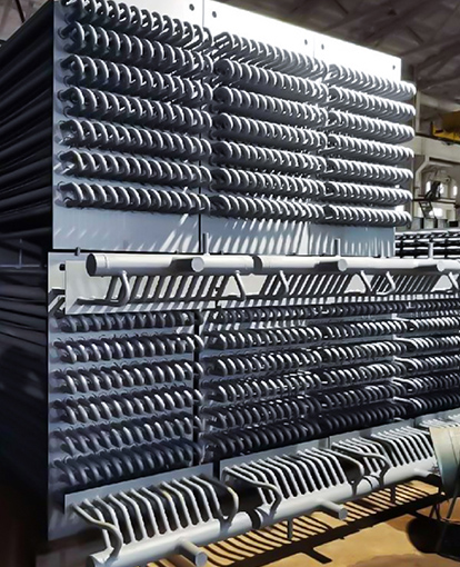
The H-shape is not a cosmetic choice. When rectangular fins are symmetrically resistance-welded to both sides of the base tube, the cross-section resembles the letter "H" — and that form creates two discrete, parallel flue gas channels along the tube length. Those channels raise local gas velocity, keep particles in suspension, and allow natural shedding of accumulated dust. The result is a surface that essentially cleans itself under normal operating conditions.
Compared with spiral finned tubes, the extended heating area of H Type Finned Tubes can be 1.5 to 2 times larger, without a proportional increase in flue gas resistance. That ratio matters: more heat transferred per unit of pressure drop means smaller, lighter heat exchanger bundles for the same duty, or higher output from an existing footprint.
Key dimensional parameters for standard production units:
| Parameter | Range / Value |
|---|---|
| Base tube OD | 25 – 65 mm |
| Tube wall thickness | ≥ 3 mm |
| Fin dimensions | 70×70 mm, 75×75 mm, 95×89 mm (custom available) |
| Fin thickness | 0.3 – 0.4 mm |
| Fin pitch | 3 – 10 mm |
| Materials | Carbon steel, stainless steel, ND steel, alloy steel |
The 3 mm minimum wall thickness is not arbitrary — it gives the tube sufficient burst pressure rating for high-temperature, high-pressure flue gas environments where waste heat is typically recovered. Research published in peer-reviewed literature confirms that convective heat transfer in H-type finned tubes responds predictably to fin pitch and fin width adjustments, giving engineers reliable levers for optimizing performance against a specific flue gas velocity profile.
Double-Finned Tubes: Structural Rigidity for Long Tube Rows
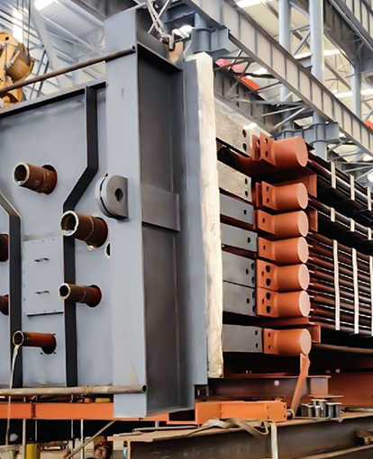
A Double-Finned Tube places two base tubes within a single shared fin set. The fins span across both tubes, locking them together mechanically and dramatically increasing the bundle's resistance to vibration and thermal sag — a real concern in long horizontal tube rows operating above 300°C.
Beyond structural advantages, the shared fin geometry increases the effective heat transfer surface even further and improves the aerodynamic separation of flue gas flow paths. Independent numerical studies on double H-type finned tube bundles show that optimized groove layouts can reduce fly ash fouling rates by up to 23.7% for particles under 20 µm, while simultaneously lifting heat transfer performance by 12–16%. That combination — more heat moved, less cleaning required — translates directly to lower lifecycle operating cost.
The weld penetration rate for high-frequency welded double-finned configurations typically reaches 97%, producing a smooth, slag-free bond line that eliminates crevices where ash could anchor itself and initiate corrosion.
Flat Finned Tube: Uniform Flow, Predictable Performance
The Flat Finned Tube variant uses the same rectangular fin welded across a single tube, distributing gas flow evenly across the entire tube surface. There are no recessed wake zones — no corners where gas slows and particles drop out of suspension. For applications with moderate dust loads and strict requirements on flue gas pressure drop, the flat fin geometry delivers consistent thermal performance without demanding high blower power to overcome flow resistance.
Engineers specifying flat finned tubes for boiler tail economizers benefit from a predictable heat transfer coefficient that holds stable across a wide range of operating loads — something spiral fins cannot reliably deliver as dust loading fluctuates through the day.
Material Selection: Matching the Tube to the Environment
Choosing the right alloy is just as important as choosing the right fin geometry. The four principal material families each cover a distinct operating zone:
- Carbon steel — cost-effective baseline for clean or mildly dusty gas below 450°C.
- ND steel (09CrCuSb) — preferred where sulfuric acid dew point corrosion is a risk; the chromium and copper additions raise corrosion resistance sharply in low-temperature economizer zones.
- Stainless steel — smooth surface finish reduces particle adhesion and handles chloride-bearing or acidic flue gas environments.
- Alloy steel — high-temperature creep resistance for applications running continuously above 550°C.
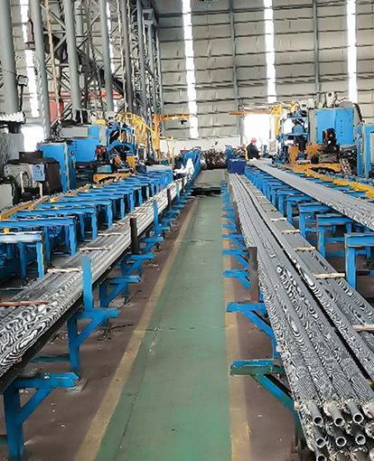
High-frequency resistance welding joins fin to tube regardless of material combination, producing a metallurgically bonded interface rather than a mechanical fit. That bond survives thermal cycling far better than mechanically attached fins and maintains full thermal conductivity across the contact zone throughout the tube's service life.
Where These Tubes Belong
The combination of high surface area, low resistance, and self-cleaning capability makes H-type geometries the standard choice across several demanding sectors. Power plant boiler economizers running on coal or biomass need surfaces that stay clean between outages. Waste heat boilers downstream of kilns, furnaces, and incinerators process gas streams heavy with particulate matter and acidic condensates. Industrial heat exchangers in the petrochemical sector demand long service intervals without internal cleaning.
All three variants — H Type Finned Tubes, Double-Finned Tubes, and Flat Finned Tube designs — cover that territory. Selecting between them comes down to tube row length (double-finned for longer, more rigid rows), dust concentration (H-type channels for heavier loading), and pressure drop budget (flat fin where resistance targets are tight).
For a detailed look at how fin geometry interacts with base tube material selection across different boiler applications, the finned tube material and type selection guide for boiler engineers covers the trade-offs in practical depth. You can also browse the full finned tube product range to compare configurations side by side.