English
  Français
  Español

Content
- 1 Why Surface Area Is Everything in Heat Transfer
- 2 Three Finned Tube Types That Cover Most Boiler Applications
- 3 Material Selection: Match the Tube to the Gas
- 4 Where Finned Tubes Fit in the Boiler Island
- 5 Key Geometric Parameters and Their Trade-offs
- 6 Maintenance: Protecting the Investment
- 7 Selecting the Right Supplier
A boiler exhausting flue gas above 300 °C is losing money with every passing minute. That thermal energy doesn't have to disappear up the stack — and that's precisely the job of the boiler finned tube. By extending the outer surface area of a plain tube with a series of fins, engineers multiply the heat exchange contact zone between hot flue gas and the working fluid inside, squeezing more energy out of every kilogram of fuel burned.
Why Surface Area Is Everything in Heat Transfer
Heat transfer between a gas and a tube wall is governed by the gas-side film coefficient — and that coefficient is inherently low. A smooth tube can only do so much. Finned tubes solve this by expanding effective surface area by 3 to 5 times compared to a bare tube of identical length and diameter. The result: faster heat exchange, lower flue-gas exit temperatures, and fuel savings of 10–15% in typical industrial boiler service.
The principle is simple — fins go on the side with the weaker heat transfer coefficient. In an economizer, that means fins on the outside, where flue gas flows. In a superheater, the same logic applies. Get the geometry right, and a compact tube bundle does the work of a much larger smooth-tube array.
Three Finned Tube Types That Cover Most Boiler Applications
Not every fin geometry suits every duty. The three types most commonly specified for boiler service each solve a different problem.
Spiral Finned Tube
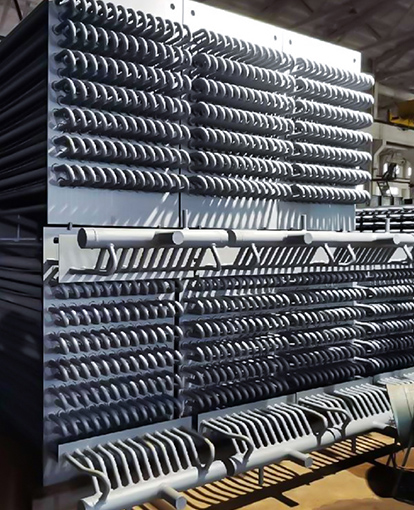
Spiral finned tubes for high-efficiency heat recovery feature continuous helical fins wound or welded around the base tube. The helical geometry promotes turbulence in the flue gas stream, improving the convective coefficient on the gas side. They are the workhorse of clean-gas boiler economizers and HRSGs, where fin spacing can be kept tight without fouling risk. Fin heights typically range from 6 mm to 25 mm; closer fin pitch increases surface area but raises gas-side pressure drop.
H-Type Finned Tube
The H-type finned tube designed for coal-fired and ash-laden boilers takes its name from the H-shaped cross-section formed by two rectangular fins welded symmetrically to opposite sides of the tube. The wide, flat fin surfaces and generous longitudinal pitch are engineered to shed ash deposits rather than trap them — a critical advantage in coal-fired boilers and biomass systems where particulate loading is high. Where spiral fins would foul and blind within weeks, H-type fins maintain effective heat transfer across long service intervals with straightforward soot-blowing maintenance.
Heat Pipe (Heat-Tube)
Heat-tube components utilizing phase-change heat transfer use evaporation and condensation of an internal working fluid to move heat with minimal temperature gradient. They are specified where isothermal operation matters — recovering waste heat at consistent temperatures for downstream processes, or in applications where condensation risk on the cold-gas side must be carefully controlled.
Material Selection: Match the Tube to the Gas
Material choice is the single most consequential specification decision. The base tube and fin must survive sustained exposure to high temperatures, pressure cycling, and corrosive flue-gas constituents — sulfur dioxide, hydrogen chloride, and nitrogen oxides all attack metal surfaces given the right conditions.
| Base Tube Material | Fin Material | Typical Application |
|---|---|---|
| Carbon steel (ASTM A192) | Carbon steel | Standard economizers, clean natural gas |
| Carbon steel | Stainless steel (304/316) | Economizers with dew-point corrosion risk |
| Alloy steel (T11, T22) | Alloy steel | High-temperature superheater sections |
| Stainless steel | Stainless steel | Aggressive flue gas, waste-to-energy boilers |
A practical cost-saving approach in economizer service is pairing a carbon steel base tube with stainless steel fins. The stainless outer surface resists acid dew-point attack while the carbon steel tube keeps material costs in check. Fin material does not always need to match the base tube — but welding compatibility must be confirmed during design.
Where Finned Tubes Fit in the Boiler Island
Finned tubes appear at every heat recovery stage of a modern boiler:
- Economizers — Preheat feedwater using residual flue gas heat, directly reducing fuel input. This is the highest-volume application, and the right economizer for boiler tail flue gas recovery can cut stack losses by a measurable margin on every operating hour.
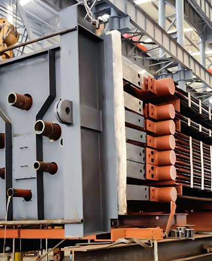
- HRSGs (Heat Recovery Steam Generators) — Combined-cycle plants route gas-turbine exhaust through finned tube bundles to generate steam without additional fuel. The industrial waste heat boiler is the defining application for high-performance finned tube bundles.
- Air Preheaters — Incoming combustion air is warmed by flue gas, improving flame temperature and combustion efficiency.
- Superheaters and Reheaters — Finned tubes in alloy grades handle the highest flue-gas temperatures in the boiler, adding superheat to the steam before it enters the turbine.
Key Geometric Parameters and Their Trade-offs
Four variables dominate finned tube thermal-hydraulic performance:
- Fin height — Taller fins add more area but reduce fin efficiency and raise gas-side pressure drop. Utility boilers typically specify 6–25 mm.
- Fin thickness — Thicker fins conduct heat better and resist erosion; thinner fins allow more fins per meter of tube, increasing area density.
- Fin pitch — Closer pitch increases surface area but traps ash in dirty-gas service. H-type fins are specified precisely because their geometry tolerates wider pitch without sacrificing performance.
- Fin density (FPI) — Fins per inch is the summary metric: 3–7 FPI for coal-fired boilers with fly ash, 8–12 FPI for clean natural-gas service.
A 1 mm ash layer on finned tube surfaces can reduce heat transfer effectiveness by 8–15% in utility boiler service. Selecting the right fin geometry from the start is cheaper than coping with accelerated fouling later.
Maintenance: Protecting the Investment
Well-designed finned tubes in clean gas service routinely achieve service lives exceeding 20 years. Aggressive environments demand more attention. The practical maintenance priorities are:
- Soot blowing — Periodic online cleaning with steam or air removes ash before it bonds to fin surfaces. H-type and stud-type fins are inherently more amenable to soot-blowing access.
- Inspection intervals — Ultrasonic thickness measurements detect wall thinning from erosion or corrosion before it becomes a safety issue. See maintenance and inspection strategies for long-life finned tube operation for a detailed framework.
- Dew-point management — Running flue gas below the acid dew point (typically 120–150 °C for sulfur-bearing fuels) corrodes fins rapidly. Controlling minimum metal temperature through feedwater inlet temperature is the primary defense.
Selecting the Right Supplier
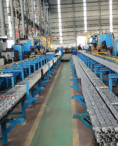
Manufacturing quality determines whether a finned tube performs as calculated or falls short. Key qualifications to verify include pressure component manufacturing licenses (Class A for headers and economizers), ASME-S stamp for international projects, and weld qualification records per ISO 3834-2. Suppliers should be able to provide documentation of fin-to-tube bond integrity — an unwelded gap between fin and tube creates a thermal resistance that defeats the entire purpose of the fin.
For engineers specifying custom finned tubes for boiler heat recovery systems, the selection process should begin with the flue-gas composition and temperature profile, move through material selection and fin geometry optimization, and close with a clear fouling and maintenance plan. Get those three steps right, and a finned tube installation delivers measurable fuel savings from day one — and keeps delivering them for decades.