English
 Français
 Español



Content
- 1 Where Chemical Processes Actually Lose Heat
- 2 Acid Dew Point Sets the Wall Temperature Floor
- 3 Economizer or Waste Heat Boiler: Match the Unit to the Duty
- 4 Finned Tubes Decide Footprint, Draft Loss and Cleaning
- 5 Code Compliance and Welding Quality Are Procurement Risks
- 6 A Specification Sequence That Survives Review
- 7 Common Questions from Chemical Process Engineers
A process heater firing 40 MW typically sends 6 to 10 MW of that energy out of the stack as sensible heat. In chemical plants the exchanger that recovers it is rarely the difficult part of the project. The difficult parts are the acid dew point of the flue gas, the fouling behaviour of the process stream, and the turndown between full rate and minimum stable operation. Settle those three properly and the heat transfer surface almost sizes itself.
20 CFlue gas drop that returns roughly one percent of fired duty
120-160 CTypical sulphuric acid dew point in chemical heater exhaust
6-10xExternal surface of a finned tube against a bare tube of equal length
Where Chemical Processes Actually Lose Heat
Recoverable heat in a chemical plant leaves through four streams: fired heater flue gas, kiln and oxidizer exhaust, exothermic reactor off-gas, and lower grade condensate. Each one carries a different constraint, and a unit designed for one duty will underperform badly on another.
Start with a measurement campaign rather than a datasheet. Log flue gas temperature, oxygen and dust loading across a full production cycle, including the burner cleaning cycle. A heater that reads 340 C at full rate often reads 290 C at night, and that 50 C swing moves the dew point margin more than any material choice you can make later.
| Stream | Typical temperature | Dominant risk | Recovery route |
| Process heater flue gas | 250 to 400 C | Sulphuric acid dew point, low load condensation | Feedwater or process fluid economizer |
| Kiln and dryer exhaust | 300 to 600 C | Dust loading, sticky alkali deposits | H-type finned economizer with retractable soot blowers |
| Thermal oxidizer outlet | 800 to 1100 C | Creep, thermal cycling, salt carryover | Radiant cooler followed by a waste heat boiler |
| Exothermic reactor off-gas | 150 to 450 C | Condensable corrosives, two phase flow | Corrosion resistant economizer with quench |
| Condensate and flash steam | 90 to 150 C | Low grade heat, contamination return | Closed loop feedwater heating |
Acid Dew Point Sets the Wall Temperature Floor
The limiting temperature in a chemical exhaust duct is the metal wall temperature, not the gas temperature. Sulphur trioxide and water vapour combine in the boundary layer and condense as liquid sulphuric acid on any surface below the dew point, and the attack starts at the fin tips where the wall is coldest.
Acid dew point: the surface temperature at which sulphur trioxide and water vapour in a flue gas condense into liquid sulphuric acid. In chemical heater exhaust it commonly falls between 120 and 160 C, and it rises with sulphur content in the feed, moisture level and excess oxygen.
Water dew point sits far lower, usually between 45 and 60 C, and is rarely the binding constraint on its own. Chloride bearing streams are a separate problem. Hydrogen chloride from chlorinated feed or from salt in waste condenses as hydrochloric acid and attacks the stainless grades that would survive a clean flue gas for a decade.
The practical options, roughly in order of cost:
- Temper the water inlet so the coldest tube wall stays 10 to 15 C above the calculated dew point, using a recirculation line or an economizer bypass.
- Specify ND steel or enamel coated tubes where the duty forces the wall temperature below what the dew point permits.
- Use cast iron or polymer lined surfaces for hydrogen chloride and chloride salt streams, even at the cost of heat transfer efficiency.
- Add a low temperature economizer stage only behind a bypass that can lift the inlet water temperature at part load. The differences between low temperature and ordinary economizers sit mostly in this control detail rather than in the tube bundle itself.
Economizer or Waste Heat Boiler: Match the Unit to the Duty
If the recovered heat is wanted as preheated boiler feedwater or as a heated process fluid, specify an economizer. If it is wanted as steam for ejectors, reboilers or a turbine, specify a waste heat boiler or heat recovery steam generator. The two are not interchangeable, and an economizer asked to raise steam will begin boiling inside its tubes within months of commissioning.
Economizer
- Single phase duty, lowest cost per kW recovered
- Needs a 15 to 30 C approach to boiling to stay stable
- Best fit when steam demand is seasonal or unstable
- Compact, lighter, easier to retrofit into an existing duct
- Sensitive to inlet water temperature at turndown
Waste Heat Boiler
- Produces steam for ejectors, reboilers or a turbine
- Requires a steam drum, level control and blowdown path
- Larger footprint and higher capital cost
- Handles high temperature streams with a radiant section
- Needs recirculation to protect the economizer at low load
A useful check is the annual steam balance. If the site can consume the steam it makes all year round, a boiler pays back faster. If steam demand is seasonal, feedwater heating through an economizer is the lower risk investment even where the boiler would recover more kilowatts on paper.
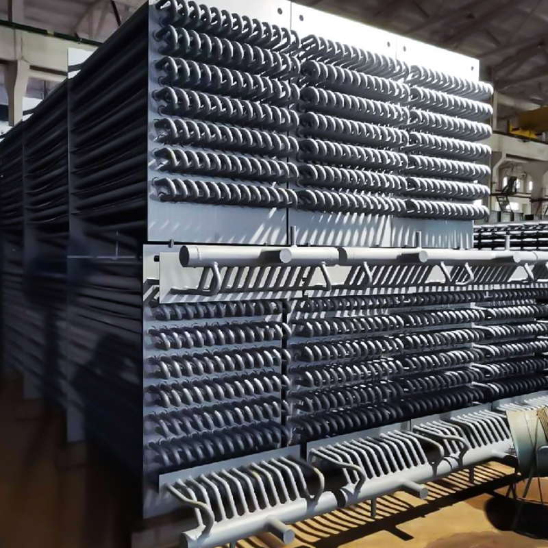 Process Equipment Flue Gas EconomizerFor seasonal steam demand, heats feedwater using process flue gas and reduces boiler load while handling corrosive or explosive exhaust.View Product →
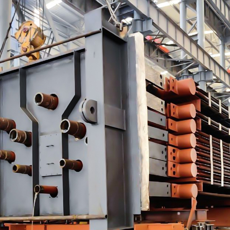 Industrial Waste Heat Recovery BoilerFor year-round steam demand, captures process waste heat to generate steam with adaptable designs for dusty or corrosive flue gas.View Product →
Finned Tubes Decide Footprint, Draft Loss and Cleaning
Extended surface is what turns an eight metre duct section into a two metre module, but the fin geometry decides how often the unit must be cleaned and how much fan power that extra surface costs.
External surface per metre of tube, relative to a bare tube
Bare tube1.0
H-type finned6.5
Spiral finned10.5
Indicative values for 32 to 38 mm tubes. The ratio shifts with fin height, fin pitch and the number of fins per inch.
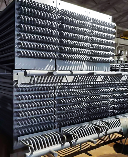
H-type finned tubes weld two half fins into an H shape on each side of the tube. The gas lanes stay straight and open, dust falls through instead of bridging between fins, and retractable soot blowers can reach the full depth of the bank. Spiral finned tubes carry more surface per metre and suit clean gas, but in sticky alkali dust the close pitch blinds over and pressure drop climbs within weeks.
Smooth tubes still have a place in heavily fouling duties where a corrosion allowance, not the heat transfer coefficient, sets the wall thickness.
Gas velocity is the quiet variable in every selection. Below about 8 m/s dust settles on the leading rows; above 12 m/s erosion on the first two rows accelerates and tube life drops sharply. Inline arrangements foul less than staggered arrangements but transfer slightly less heat per row, which is usually the right trade in chemical service.
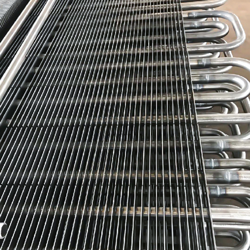 H-Type Finned Tube for Dust-Laden Flue GasH-shaped fins limit dust deposition and keep flue-gas resistance low, suiting waste-heat exchangers where fouling and velocity control matter.View Product →
Code Compliance and Welding Quality Are Procurement Risks
Pressure part compliance decides who signs the thermal design and who carries the risk if a tube fails. It is not paperwork attached to a heat exchanger after the thermal calculation is finished.
- Design code stamp: ASME Section I for steam generating units, Section VIII Division 1 for unfired exchangers.
- Material certification to EN 10204 3.1 with heat numbers traceable to the mill certificate.
- Welding procedure and welder qualification records held to ISO 3834-2.
- Radiography or real time X-ray imaging of tube to header joints, with a film library that matches the weld map.
- Hydro test records and dimensional reports issued before shipment, not after arrival.
Ask for the weld map and the radiograph of the first tube to header joint before the purchase order is placed, not after the factory acceptance test.
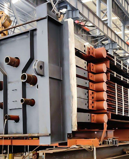
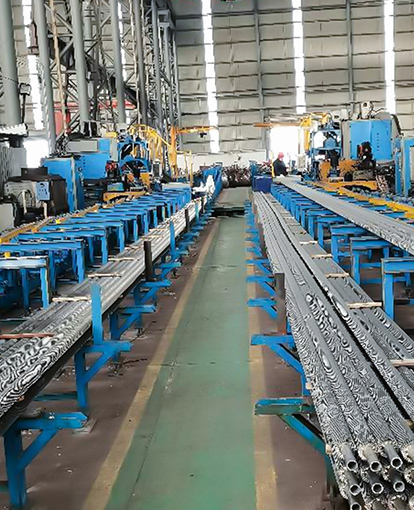
Fabricators that weld, radiograph and hydro test inside the same plant can answer that request during the bid. A supplier with automated welding lines, in house X-ray imaging and a documented quality system, such as the team described in this manufacturing capability profile, is easier to audit than a trading company assembling packages from several sub vendors.
A Specification Sequence That Survives Review
Most failed specifications come from fixing the equipment type before the process data is settled. Work through these five steps in order and the thermal design follows without argument.
- Fix the duty and the turndown range. State recovered heat in kW at full rate, at 70 percent and at minimum stable rate, and confirm which of the three governs the surface area.
- Characterise the stream. Composition, sulphur content, moisture, chloride level and dust loading, with the acid dew point calculated rather than assumed.
- Set the pinch. Choose the exit gas temperature 10 to 15 C above the calculated dew point, then check the water side approach at part load, not just at design rate.
- Select the surface. Pick the fin type from the dust load, set the gas velocity between 8 and 12 m/s, and size soot blowers or water washing access at the same time.
- Lock inspection and delivery. Add a fouling allowance of 10 to 20 percent extra surface and confirm the weld map, NDT scope and hydro test schedule in the purchase order.
Common Questions from Chemical Process Engineers
What is the minimum safe flue gas exit temperature for a chemical plant economizer?
It follows the acid dew point rather than a fixed number. With ten percent moisture and low sulphur, the dew point sits near 120 C; heavy sulphur in the feed pushes it beyond 150 C. Keep the exit gas 10 to 15 C above the calculated value and temper the water inlet so the coldest wall stays clear of condensation at part load.
Which finned tube suits dust laden chemical exhaust?
H-type finned tubes in an inline arrangement. The straight gas lanes resist bridging and the open pitch allows retractable soot blowers to clean the full depth of the bank. Spiral finned tubes are the better choice only when the stream is clean and footprint is the binding constraint.
Can a waste heat boiler run at 40 percent load?
Yes, provided the design includes economizer recirculation, three element drum level control and a bypass damper that holds the evaporator inlet temperature above dew point at low load. Without recirculation, the economizer becomes the first component to fail during winter turndown.
How much fouling allowance should be specified?
Ten to twenty percent additional surface for clean gas and up to twenty five percent for sticky alkali dust, always paired with gas side access for cleaning. Buying the extra surface without the cleaning access is the most common specification mistake in chemical service.