English
 Français
 Español



Content
Industrial heat transfer
On a 120 t/h gas-fired boiler, flue gas leaving the economizer sits near 145 C. Bypass that economizer and the same stack runs at roughly 260 C. Closing that 115 K gap is worth about five percent of the fuel bill, every hour the plant runs.
That gap is what industrial heat transfer work is really about. It is rarely a question of exotic alloys or new thermodynamics; it is a question of surface area, gas velocity, fouling allowance and where the metal sits inside the duct. Get those four right and a plain design outperforms an elegant one that plugs solid in six weeks.
The sections below cover the mechanisms, the hardware, the selection steps and the numbers that decide whether a project gets approved or shelved.
What Industrial Heat Transfer Really Covers
Industrial heat transfer is the controlled movement of thermal energy between a hot stream, a cold stream and the metal separating them, and in heavy industry the hot stream is almost always flue gas on its way to the stack.
Definition: industrial heat transfer is the design of surfaces and flow paths that move heat from combustion gas, process exhaust or steam into a useful fluid, fast enough to pay for the equipment and gently enough to keep the tube wall above its corrosion limit.
Three mechanisms share the duty. Radiation dominates above roughly 800 C, which is furnace territory. Conduction through the tube wall is almost never the bottleneck, because a 3 mm carbon steel wall at 400 C adds negligible resistance. Convection on the gas side does the damage.
Clean flue gas at 10 to 15 m/s gives a film coefficient of roughly 30 to 60 W/m2K. The water or steam side of the same tube runs above 1000 W/m2K. Since resistances add in series, the gas side owns about 90 percent of the problem, and every downstream design decision follows from that single fact.
1%approximate fuel saving per 20 K drop in stack temperature
4-8xexternal surface added by H-type or spiral fins
18-30months of typical simple payback on an economizer retrofit
The practical consequence is simple. Add area on the gas side, keep gas speed high enough to scour the fins but low enough to avoid erosion, and accept that the tube wall will run close to the water temperature. Everything else is detail.
The Surfaces That Decide Your Heat Transfer Rate
The gas-side surface is where a heat recovery design is won or lost, so finned tubes, economizer banks and HRSG modules are judged on the same three numbers: surface density, gas velocity and fouling tolerance.
| Element | Typical duty | Gas-side exit | Dominant risk |
| Bare tube bank | Small economizer or air preheater | 180 to 220 C | Low surface density, large footprint |
| H-type finned tube | Economizer in ash-bearing flue gas | 150 to 190 C | Ash bridging between fin pairs |
| Spiral finned tube | Clean-gas economizer, HRSG evaporator | 120 to 160 C | Fin-root corrosion near the dew point |
| HRSG module | Combined cycle exhaust | 80 to 100 C stack | Thermal stress at attemperator and drum |
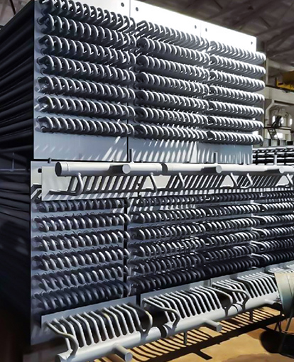
H-type fins are welded in pairs with a straight gas lane between them, which is why they survive coal and biomass ash that would plug a dense spiral bank. Spiral fins give more area per metre and better performance in clean gas, but they are harder to clean and far less forgiving of cold spots.
The detail most often missed is fin efficiency. Long, thin fins at high temperature conduct poorly along their length, so the effective area is smaller than the geometric area. If a datasheet quotes area without a fin efficiency figure, ask for it before you compare prices. A separate note on how finned tubes raise heat transfer efficiency walks through the surface calculation in more detail.
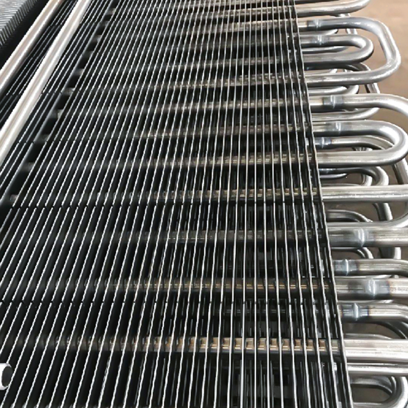 H-Type Finned Tube for High-Efficiency Heat TransferHigh-frequency welded H-shaped fins increase heating area and resist dust, making fin efficiency worth checking before comparing heat-transfer options.View Product →
Rule of thumb: if the ash is sticky, choose the fin geometry with the widest gas lane you can afford, then buy back the lost area with a deeper bank rather than a denser fin pitch.
Where the Heat Actually Escapes
Most plants lose recoverable heat in three places: the stack, hot surfaces that were never re-insulated after a modification, and blowdown or condensate that is dumped instead of returned.
Worth recovering
- Flue gas above 180 C at full load
- Continuous blowdown above 5 percent of steam flow
- Condensate returning above 90 C
- Steam trap losses on a header running 24/7
Usually not worth it
- Intermittent exhaust from batch processes
- Gas below the acid dew point with no corrosion allowance
- Surface losses on lines already under 50 C skin temperature
- Small streams needing their own pump and control loop
Two numbers decide how far the gas temperature can be pushed. The acid dew point sets the floor: with 1 to 2 percent sulphur fuel, water vapour and SO3 begin condensing on the fins somewhere between 120 and 150 C. The pinch point sets the practical limit for steam generation, usually 8 to 15 K between gas leaving and steam saturating.
Field note: a 12 K lower gas outlet looks like free efficiency on paper, but if it puts the fin root under the dew point for 300 hours a year, the tube gets replaced long before the fuel saving is banked.
When the gas is above roughly 500 C, an economizer is the wrong tool entirely. That duty belongs to a waste heat boiler that generates steam or heats a process fluid, and the decision is driven by the plant steam balance far more than by the gas data.
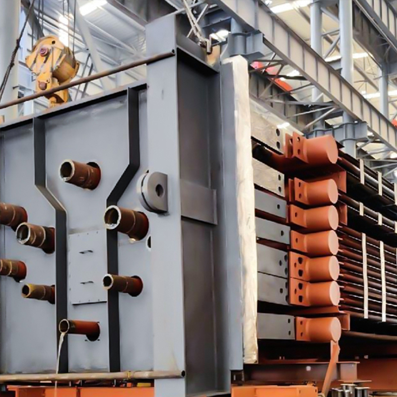 Industrial Waste Heat Boiler for High-Temperature Flue Gas RecoveryFor flue gas above economizer range, this boiler recovers heat to generate steam and adapts to dust, corrosion, and fluctuating sources.View Product →
Matching Equipment to the Duty
Equipment selection follows the gas condition first and the steam or water demand second, never the other way round.
- Fix the gas data: flow, temperature, composition, dust loading, dew point, and how all four shift between summer and winter.
- Set the target outlet temperature with a corrosion margin, not at the theoretical optimum.
- Size the surface with an honest fouling factor, around 0.005 to 0.01 m2K/W for clean gas and two to three times that for oil firing or biomass.
- Check the layout and tie-in: duct space, fan head, drum elevation, bypass arrangement and physical access for cleaning.
Steps three and four are where budgets are lost. A unit sized for a clean duty and installed without a sootblower needs an unscheduled outage within two years, and the cost of adding one later usually exceeds the price difference between a cheap design and a good one.
On EPC work the interface matters as much as the thermal design. Duct transitions, expansion joints, support steel and instrumentation all have to be resolved in 3D before fabrication starts, which is why a supplier who can convert drawings and verify heat input in-house saves a project more time than a supplier who simply quotes a lower price per tonne. The company profile sets out that engineering scope in more detail.
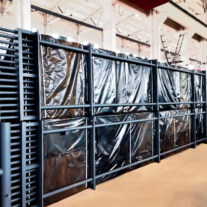 Boiler Tail Flue Gas EconomizerRecovers boiler tail-flue heat to preheat feedwater, cut fuel use, and suit coal, gas, oil, biomass, or waste-heat boiler systems.View Product →
A design that gains three percent more efficiency but forces a cleaning outage every quarter is not an improvement. It is a maintenance contract with a heat transfer attachment.
Reading the Economics Before You Commit
Payback on industrial heat transfer equipment is dominated by annual running hours and fuel price, not by small differences in thermal efficiency.
8000 h/yr14 mo
6000 h/yr19 mo
4000 h/yr28 mo
2000 h/yr56 mo
Simple payback in months for a 20 K stack temperature reduction, gas at roughly 6 USD per MMBtu, before maintenance and outage costs.
Three inputs decide whether the case survives a review meeting:
- Operating hours at realistic load, not nameplate hours.
- Fuel cost across the equipment life, with a sensitivity check at half the current price.
- Cleaning and inspection cost, including the outage days it consumes.
Add pressure-part compliance early. ASME or PED documentation, material traceability and third-party inspection rarely change the thermal design, but they can move the delivery schedule by months if they are raised after the drawing is frozen.
The short version: measure the gas, respect the dew point, size for fouling, and check running hours before you compare efficiency figures.
Frequently Asked Questions
What is the difference between an economizer and a heat recovery steam generator?
An economizer heats feedwater without changing its phase, typically using flue gas at 200 to 400 C. A heat recovery steam generator produces steam and usually contains economizer, evaporator and superheater sections in one casing, recovering exhaust from gas turbines or high temperature processes.
What stack temperature should I target?
As low as the acid dew point and the pinch point allow. For low-sulphur gas this is often 120 to 150 C; for high-sulphur fuel oil it can be 160 C or higher unless corrosion-resistant fins are specified.
How do I keep finned tubes from fouling?
Match the fin type to the ash, hold gas velocity in the 8 to 12 m/s range, and install sootblowers with enough lanes to reach the tube wall. H-type fins with wide gas lanes are the safer choice below 300 C where ash is sticky.
Can heat recovery equipment be retrofitted into an existing duct?
Yes, if fan head and duct space allow it. Most retrofits need a bypass for turndown and cleaning, and the extra draft loss of 0.5 to 1.5 kPa usually has to be paid for with a fan upgrade or a taller stack.
Thermal design is a compromise between area, velocity and cleanliness. Pick two and the third will invoice you later.