English
  Français
  Español

Content
Why Finned Tubes Dominate Boiler Heat Recovery
In a waste heat boiler operating at 350 °C, a bare tube bank typically yields an overall heat transfer coefficient of 20–30 W/m²K. Replace those tubes with finned equivalents, and that value can climb to 60–80 W/m²K — often with fewer tube rows. The reason is simple geometry: fins extend the heat transfer surface area by a factor of 10 to 25 compared to the base tube surface, dramatically increasing the heat duty per tube length.
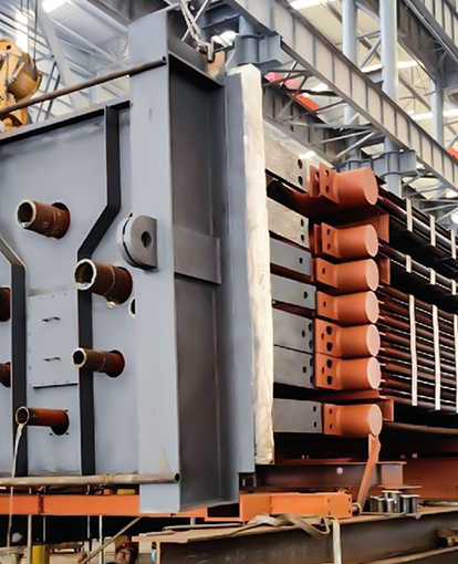
Boiler finned tubes are core components in economizers, superheaters, and waste heat recovery units. By attaching metallic fins to the outer surface of a tube, you increase the area available for convective heat exchange while keeping the tube count low. This translates directly into lower weight, reduced footprint, and lower manufacturing cost for heat recovery equipment. Engineers specify finned tubes whenever gas-side heat transfer coefficients are much lower than the water-side coefficients — the common case in boiler flue gas applications.
How Finned Tubes Multiply Heat Transfer
The physics is rooted in the extended surface equation. The fin's temperature decreases from its base toward the tip, so only a portion of the fin area performs at full driving force. The fin efficiency — often 0.7 to 0.95 — multiplies the theoretical area. A well-designed tube with 25 times the bare surface might deliver 18 to 22 times the heat transfer, provided the gas flow is sufficiently turbulent.
Pressure drop is the trade-off. Tighter fin pitches produce higher heat transfer but also increase gas-side resistance. A pitch of 4 to 6 fins per inch is common for clean fuels; for high-ash or sooty gases, designers drop to 2–4 fins per inch or switch to H-type finned tubes that resist plugging. The balance between thermal performance and fan power defines the economic optimum.
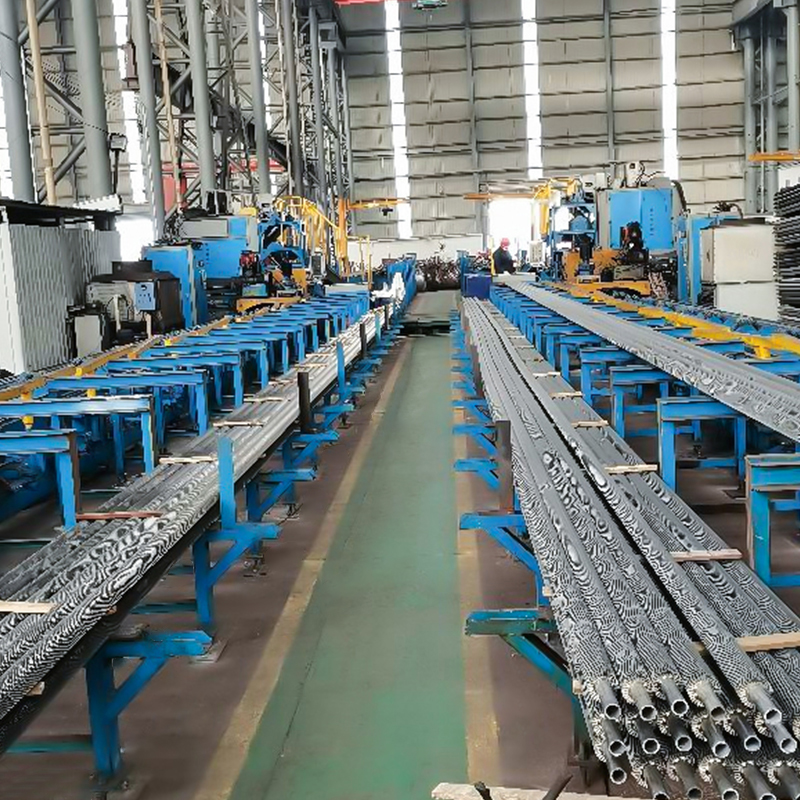
Types of Boiler Finned Tubes
Finned tube geometry is dictated by the fuel, gas composition, and maintenance regime. Three configurations cover the majority of boiler applications.
H-Type Finned Tubes
Widely used in coal-fired and biomass boilers, H-type fins consist of two rectangular plates welded to opposite sides of the tube. The open channel design lets ash fall through rather than accumulate. This geometry also allows complete welding, eliminating crevices that trap corrosive deposits. For high-dust environments, H-type finned tubes offer a rugged solution with manageable cleaning requirements.
Spiral Finned Tubes
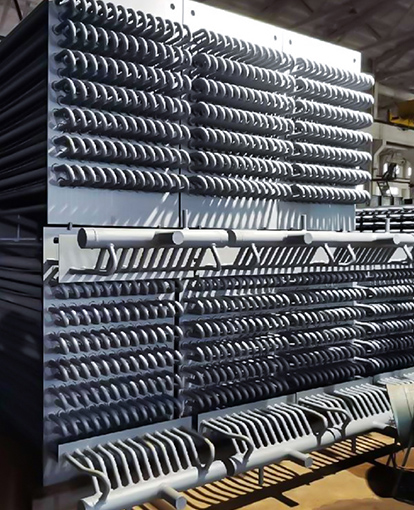
Spiral fins wrap continuously around the tube, creating a compact and economical extended surface. They perform best in clean gas streams — such as natural gas-fired economizers — where fouling is minimal. Spiral finned tubes use strip steel wound under tension and welded at the base; bond integrity is critical. Gaps become hot spots and corrosion initiation sites.
Longitudinal Finned Tubes
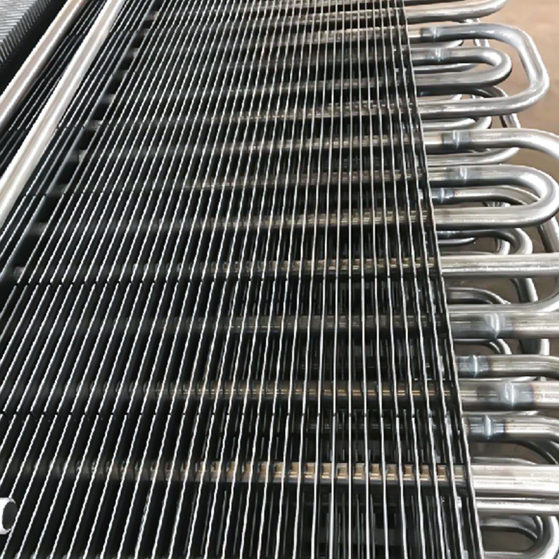
Longitudinal fins run parallel to the tube axis and are used in cross-flow where gas flows perpendicular to tubes. They provide lower pressure drop than spiral fins and suit applications with moderate fouling. However, they are less efficient than H-type or spiral for pure counterflow designs and are more common in specialized heater batteries than in mainstream boiler economizers.
Material Selection for Finned Tubes
Both tube and fin must withstand the flue gas temperature, chemical attack, and erosion. Carbon steel grades SA 179 and SA 192 dominate for economizers up to 450–500 °C. Above that, low-alloy steels containing chromium and molybdenum (T11, T22) resist creep and oxidation. Stainless steel grades like 304 and 316 step in when sulfur or chlorides threaten corrosion. The table below summarizes typical material limits.
| Material | Max Service Temperature (°C) | Corrosion Resistance | Typical Use |
|---|---|---|---|
| Carbon Steel (SA 179) | 450 | Low | Clean gas economizers |
| Carbon Steel (SA 192) | 500 | Low | Boiler water walls |
| 1.25Cr-0.5Mo (SA 213 T11) | 560 | Moderate | Superheaters, HRSGs |
| 2.25Cr-1Mo (SA 213 T22) | 580 | Moderate | High-temperature sections |
| 304 Stainless Steel | 800 | High (oxidation) | Corrosive flue gas, high-temp |
| 316 Stainless Steel | 800 | High (chloride) | Marine boilers, chloride environments |
Fin material can differ from the tube. For example, carbon steel fins on a stainless tube combine corrosion resistance where it matters with lower cost on the extended surface. Always confirm the fin attachment method — brazed, high-frequency welded, or embedded — to ensure compatibility with thermal cycling and gas chemistry.
Design Parameters That Drive Performance
Selecting fin height, thickness, and pitch is not a guessing game. Each parameter affects thermal and hydraulic performance in measurable ways.
- Fin height: Taller fins increase area but reduce fin efficiency because the tip temperature drops further below the base temperature. Optimal height is typically 0.5 to 1.5 times the tube outside diameter.
- Fin thickness: Thicker fins conduct heat better but add weight and cost. For carbon steel, 0.8–1.5 mm is standard; stainless may be thinner.
- Fin pitch: Closer spacing packs more area but raises pressure drop and the risk of bridging by fouling. Start with 4–6 fins per inch for clean gas, 2–4 for dirty gas.
- Tube diameter and arrangement: Staggered tube layouts enhance turbulence and heat transfer at the expense of higher pressure drop. In-line arrangements permit easier cleaning.
Manufacturers often provide performance correlations based on wind-tunnel testing. Even small adjustments — moving from 5 to 4 fins per inch — can cut gas-side pressure drop by 20–30% while sacrificing less than 10% of the heat transfer coefficient. Detailed engineering analysis helps weigh these trade-offs before procurement.
Maintenance and Longevity
Finned tubes live in harsh environments. Ash, soot, and corrosive condensates accumulate between fins, reducing heat transfer and promoting under-deposit corrosion. Steam or air sootblowers are the first line of defense, but their effectiveness depends on tube layout and fin geometry. H-type fins, with their open architecture, respond far better to sootblowing than tightly packed spiral fins.
Inspection intervals should follow the same schedule as the boiler itself. Look for fin deformation, weld cracking, and signs of high-temperature oxidation. Spot repairs are possible with individual tube replacement, but a systematic approach outlined in maintenance and inspection strategies yields longer tube life and fewer forced outages.
Selecting the Right Finned Tube for Your Boiler
Start with three data points: fuel type, flue gas composition, and target exhaust temperature. A natural-gas-fired boiler with clean exhaust can use tightly pitched spiral fins on carbon steel. Switch to heavy fuel oil or coal, and you need H-type or widely pitched spiral fins in an alloy that withstands sulfur dew-point corrosion. For waste heat recovery from kilns or incinerators with aggressive gases, stainless steel fins become mandatory.
Procurement should specify not only materials and geometry but also acceptable bond quality — 100% ultrasonic testing of fin-to-tube welds for critical applications, for instance. The cost of a finned tube is small relative to the cost of lost generation when an economizer fails. A thorough specification closes the loop between design intent and decades of reliable operation.