English
 Français
 Español



Content
A 250 MW coal-fired unit with post-combustion capture can send 1.2 to 1.6 million tonnes of flue gas through its absorber every year. The absorber itself is usually not the limiting item. The harder problems are thermal: cooling the flue gas from 140°C to roughly 45°C, supplying 100 to 150 tonnes per hour of low-pressure steam to the reboiler, and keeping the heat-exchange surfaces clean and corrosion-resistant for a 20-year campaign.
That is why carbon capture units should be specified as integrated heat-recovery systems, not as a standalone column plus a solvent package. The equipment that handles flue gas cooling, condensate heating, and reboiler steam generation determines whether the capture plant meets its energy penalty target or quietly consumes more steam than the design case promised. This article explains where those thermal duties sit, which components carry them, and what to check before issuing a purchase order.
Why Carbon Capture Units Are Thermal Systems First
Most operating carbon capture units use aqueous amine solvents. The regeneration step is the largest continuous heat load. Depending on solvent formulation, CO2 loading, and stripper pressure, the reboiler consumes roughly 2.8 to 3.6 GJ per tonne of CO2 captured. For a 1 million tonne per year capture plant, that translates into 100 to 150 tonnes per hour of saturated steam, usually at 0.3 to 0.5 MPa. If the steam comes from an existing turbine cycle, it reduces net power output; if it comes from an auxiliary boiler, it adds fuel cost and emissions.
Three thermal duties dominate the balance of plant:
- Flue gas cooling and water removal before the absorber, typically from 120–160°C down to 40–50°C.
- Reboiler steam supply at stable pressure and temperature, with low carryover risk.
- Lean/rich solvent heat exchange and CO2 product cooling, which influence solvent degradation and compression energy.
Each duty has a different equipment answer. The common thread is that extended-surface heat exchangers and waste-heat recovery boilers can recover energy that would otherwise be rejected to cooling water or the stack. That recovery directly offsets the capture plant’s steam demand.
Flue Gas Cooling and Heat Recovery
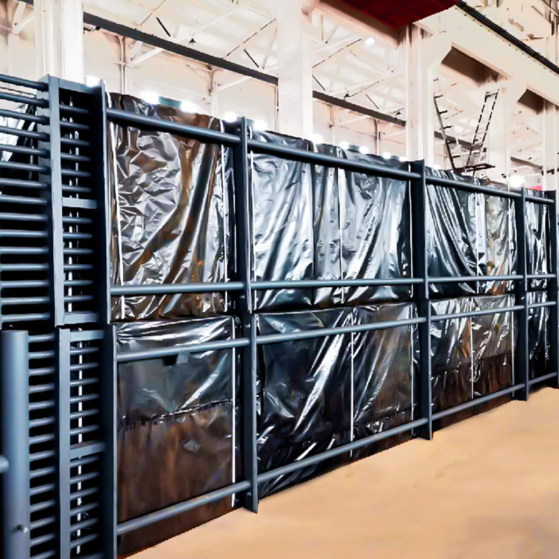 Economizer for Boiler Tail Flue GasInlet Flue Gas Temperature | 120-200°C | | Outlet Flue Gas Temperature | 100-150°C | | Inlet Feedwater Temperature | 80-120°C | | Outlet Feedwater Temperature | 150-20...View Product →
At the inlet to a capture unit, flue gas is too hot and too wet for most amine absorbers. Direct quench with water is simple, but it consumes treated water and sends the recovered heat to the atmosphere. An indirect heat exchanger recovers sensible heat while cooling the gas to the absorber window. The recovered heat can preheat boiler feedwater, district heating return water, or combustion air.
For coal- and biomass-fired units, the flue gas cooling section often looks like a low-temperature economizer. The design challenge is not the heat transfer coefficient; it is the acid dew point. When the tube wall drops below the sulfuric acid dew point, condensation forms and corrosion begins. The practical solution is to keep the metal temperature above the dew point during normal operation, or to specify corrosion-resistant materials such as ND steel, Corten, or stainless steel where the duty cannot avoid condensation.
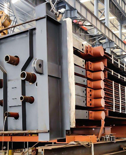
A tail-end flue gas economizer is a common choice because it can be integrated downstream of the existing air preheater, using the captured heat to raise feedwater temperature or to generate low-pressure steam. The same unit can reduce the cooling load on the direct contact cooler, which lowers water consumption and chemical dosing. In a capture retrofit, this is often the lowest-cost way to claw back part of the energy penalty.
Steam Supply for Regeneration: HRSG and Waste Heat Boiler Roles
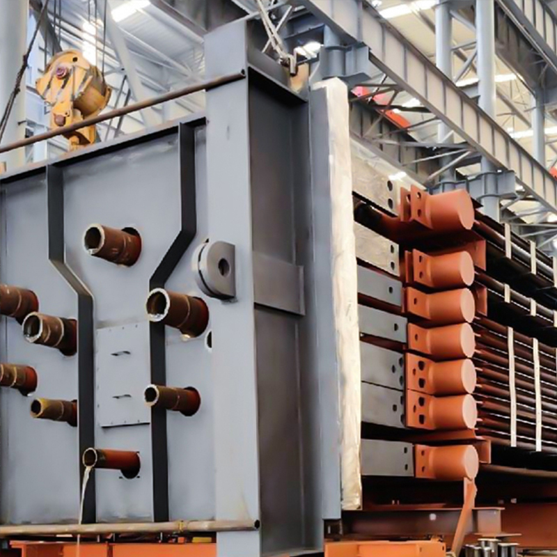 Industrial Waste Heat BoilerFlue gas volume |320,000 Nm³/h| | Inlet flue gas temperature |450°C| | Outlet flue gas temperature |100°C| | Steam evaporation rate |3.8-54.5 t/h| | Steam pressure |0....View Product →
Carbon capture units need steam, and they need it reliably at the reboiler. In combined-cycle power plants, the heat recovery steam generator (HRSG) can supply extraction steam from an intermediate pressure stage. In industrial sites, a waste heat boiler can recover heat from kiln exhaust, process off-gas, or gas turbine exhaust to produce the required steam. The key selection question is whether the steam source can follow the capture plant’s load profile without upsetting the host process.
A waste heat boiler designed for capture service must handle two operating modes: normal capture operation and capture bypass. During bypass, the boiler may see higher flue gas temperatures or different flow rates. The control system, drum sizing, and superheater or evaporator surfaces must tolerate both. If the reboiler requires saturated steam, the boiler should be specified with adequate steam space and separator efficiency to avoid carryover, which can foul solvent and damage the stripper.
Where the host plant already has an HRSG, the capture unit may be able to use low-pressure steam from the low-pressure drum or an extraction. That is often cheaper than a new boiler, but it is not free: the steam has already passed through a turbine stage, so using it for regeneration reduces electricity output. A dedicated waste heat boiler can sometimes recover heat from a stream that would otherwise be vented, turning a waste stream into reboiler duty.
Component Selection: Finned Tubes, Materials, and Cleaning
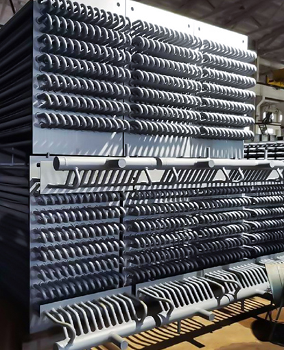
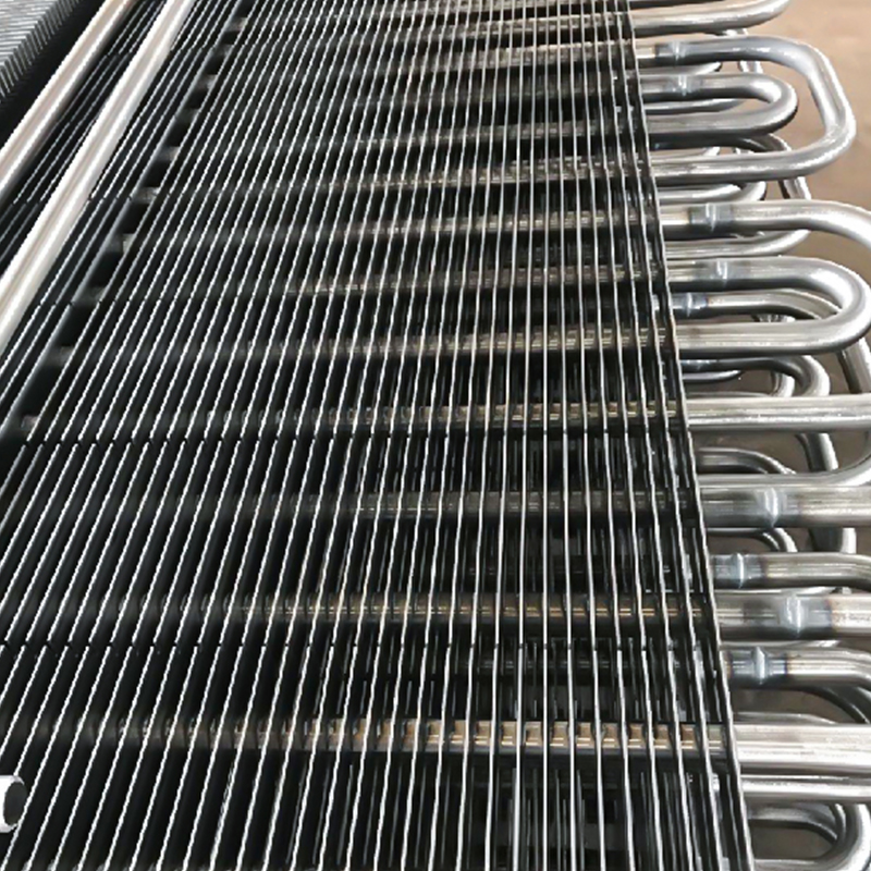 H type Finned TubeTube OD 25-65mm Tube wall thickness ≥3mm Fin dimensions 70mm×70mm, 75mm×75mm, 95mm×89mm, etc. Fin thickness 0.3-0.4mm Fin pitch 3-10mm Material: Carbon steel, stainles...View Product →
Inside the capture unit’s flue gas cooler, economizer, and reboiler feedwater preheater, the tube surface does the work. Extended surfaces increase the gas-side area without increasing the pressure envelope. The choice between H-type finned tubes, spiral finned tubes, and smooth tubes affects heat transfer, fouling, and cleaning strategy.
| Parameter | H-type finned tube | Spiral finned tube | Smooth tube |
|---|---|---|---|
| Heat transfer area per unit length | Moderate to high | High | Low |
| Fouling resistance in ash-laden gas | Good; open channels resist bridging | Moderate; fin gaps can plug | Good but large footprint |
| Cleaning method | Soot blowers, water wash | Soot blowers, careful water wash | Soot blowers, mechanical cleaning |
| Typical fit in capture unit | Flue gas cooler, economizer | Clean gas or low-fouling duty | High-temperature or abrasive duty |
Material selection follows the same logic. Carbon steel is acceptable above the acid dew point. For lower metal temperatures, consider corrosion-resistant grades or a protective coating. The tube-to-header joint is a critical weld: it must be leak-tight under thermal cycling, because even a small leak can contaminate the solvent loop or create a cold spot that accelerates corrosion.
Fouling and cleaning access should be decided at the layout stage. A capture unit that looks efficient on a heat and mass balance can lose 10–15% of its heat transfer performance within a few months if soot blowing lanes are blocked or the tube pitch is too tight for the expected ash loading. H-type finned tubes are often chosen for coal-derived flue gas because their straight channels are easier to clean than dense spiral fins.
Procurement and Engineering Risk Checks
The heat exchangers and waste heat boilers in a carbon capture unit are pressure parts. They must be designed, welded, inspected, and documented to a recognized code. In most international projects, ASME Boiler and Pressure Vessel Code Section I or Section VIII applies, depending on the component and jurisdiction. ISO 9001 and ISO 3834-2 provide the quality management and welding fabrication framework. For a practical checklist of pressure-part compliance, see this ASME pressure-part compliance guide for engineers.
Before awarding a contract, ask three questions:
- Can the supplier perform thermal rating and mechanical design together, or are they passing a datasheet to a fabricator? Capture units often have tight plot space and variable flue gas conditions. A supplier that can run heat input checks and convert project drawings into fabrication drawings reduces interface risk.
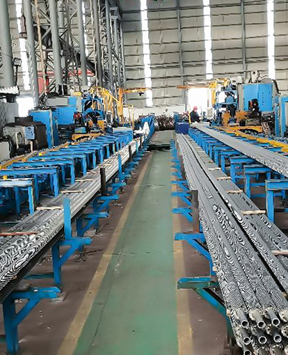
- What is the welding and inspection plan? Automated welding lines plus radiographic or X-ray real-time imaging are not marketing details; they determine whether tube-to-header welds pass a helium leak test and survive thermal cycling.
- What is the delivery and capacity evidence? Large EPC projects need tonnage visibility. A fabricator with annual output above 20,000 tonnes and experience in power, petrochemical, and heavy industry can usually absorb schedule changes better than a small workshop.
It also helps to review the manufacturer’s engineering background and export experience before the technical bid clarification. For projects in multiple jurisdictions, documentation packages, material traceability, and third-party inspection coordination matter as much as the thermal design. A supplier that has delivered to more than 50 countries is more likely to have procedures for those requirements already in place. You can review the manufacturer’s engineering and fabrication background as part of the prequalification process.
Carbon capture units succeed or fail on heat integration. The absorber and solvent get most of the attention, but the flue gas cooler, economizer, waste heat boiler, and finned-tube surfaces decide how much steam the reboiler actually needs and how much of the plant’s energy penalty can be recovered. Start the thermal specification early, keep the acid dew point and fouling margins visible in the layout, and choose pressure-part suppliers who can demonstrate code compliance, welding quality, and capacity for large EPC delivery. Done well, the heat recovery equipment is not an add-on to the capture unit; it is the part that makes the capture unit economically sustainable.