English
 Français
 Español



Content
A 20 t/h industrial boiler that sends flue gas up the stack at 180 degrees Celsius is throwing away roughly 8 to 12 percent of the fuel energy it just paid for. Cut that exit temperature by 20 degrees with a correctly sized economizer and overall thermal efficiency usually gains about one percentage point. On a plant running 7,000 hours a year, that is not a rounding error. The engineers who capture the largest gains treat heat transfer as a system-level design problem rather than a component purchase.
What a Heat Transfer System Actually Does
A heat transfer system is the engineered combination of transfer surfaces, fluid flow paths, structural supports and controls that moves thermal energy from a hot source to a colder sink at a controlled, measurable rate.
That definition matters because most plant problems blamed on poor heat transfer turn out to be problems of surface area, flow distribution, fouling or temperature approach. The physics itself is rarely the surprise.
In industrial service, three mechanisms share the work, and their proportions shift with temperature.
| Mechanism | What carries the energy | Where it dominates | Typical hardware |
| Conduction | Molecular vibration and free electrons | Through solid walls and tube metal | Finned tubes, tube sheets, headers |
| Convection | Moving fluid particles | Gas side and water or steam side | Economizers, superheaters, air preheaters |
| Radiation | Electromagnetic waves | Flame and furnace zones above about 900 degrees Celsius | Furnace water walls, combustion chambers |
Radiation grows with the fourth power of absolute temperature, so furnace designers stop arguing about gas velocity above roughly 900 degrees Celsius and start arguing about view factors instead. Below about 400 degrees Celsius the situation reverses: convection sets the duty and surface area becomes the only lever worth pulling.
The practical consequence is that a heat transfer system is sized around its weakest film coefficient. If the gas-side coefficient sits ten times lower than the water-side coefficient, doubling tube wall conductivity buys almost nothing.
Core Components That Carry the Duty
Four component families do most of the work in industrial heat transfer systems: finned tubes, economizers, heat recovery steam generators, and the structural and control hardware that holds them together.
Finned tubes: the surface multiplier
A bare tube can only shed so much heat because the gas-side film coefficient sits an order of magnitude below the water or steam side. Finned tubes extend the outer surface without enlarging the bundle footprint, which moves the bottleneck back inside the tube where it belongs. The trade-off is fouling, because tighter fin spacing means more surface and also more places for ash to bridge.
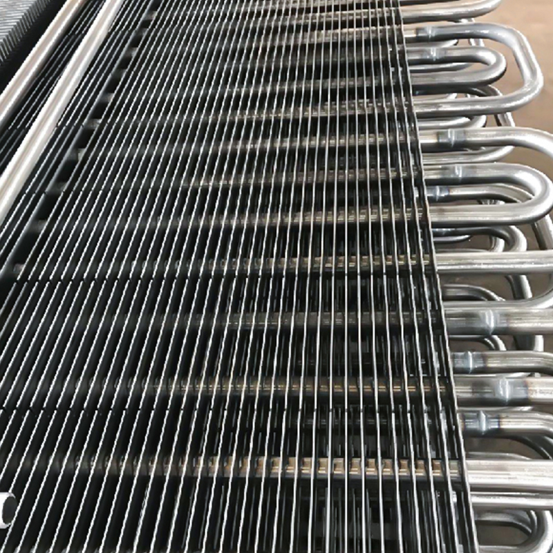 H type Finned TubeTube OD 25-65mm Tube wall thickness ≥3mm Fin dimensions 70mm×70mm, 75mm×75mm, 95mm×89mm, etc. Fin thickness 0.3-0.4mm Fin pitch 3-10mm Material: Carbon steel, stainles...View Product →
Economizers: the cheapest gain on the boiler
An economizer sits in the boiler tail duct and pulls heat out of the flue gas before it leaves the system. It is the lowest-cost recovery device because it has no combustion-side requirements and can be retrofitted as a stand-alone module. The engineering risk is almost never the heat balance. It is keeping the tube wall above the acid dew point during part-load operation.
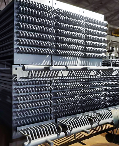
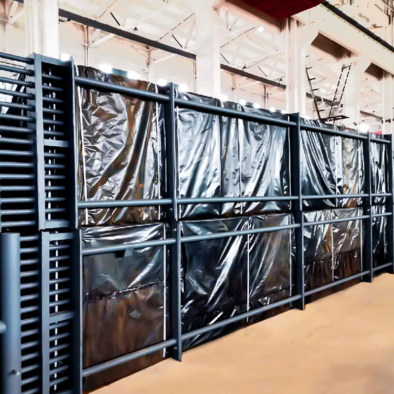 Economizer for Boiler Tail Flue GasInlet Flue Gas Temperature | 120-200°C | | Outlet Flue Gas Temperature | 100-150°C | | Inlet Feedwater Temperature | 80-120°C | | Outlet Feedwater Temperature | 150-20...View Product →
Heat recovery steam generators: turning exhaust into steam
A heat recovery steam generator, usually shortened to HRSG, converts high-temperature exhaust into usable steam. In combined cycle plants the gas turbine exhaust arrives at the HRSG inlet somewhere between 450 and 600 degrees Celsius, and that energy is enough to drive a steam turbine without burning any additional fuel.
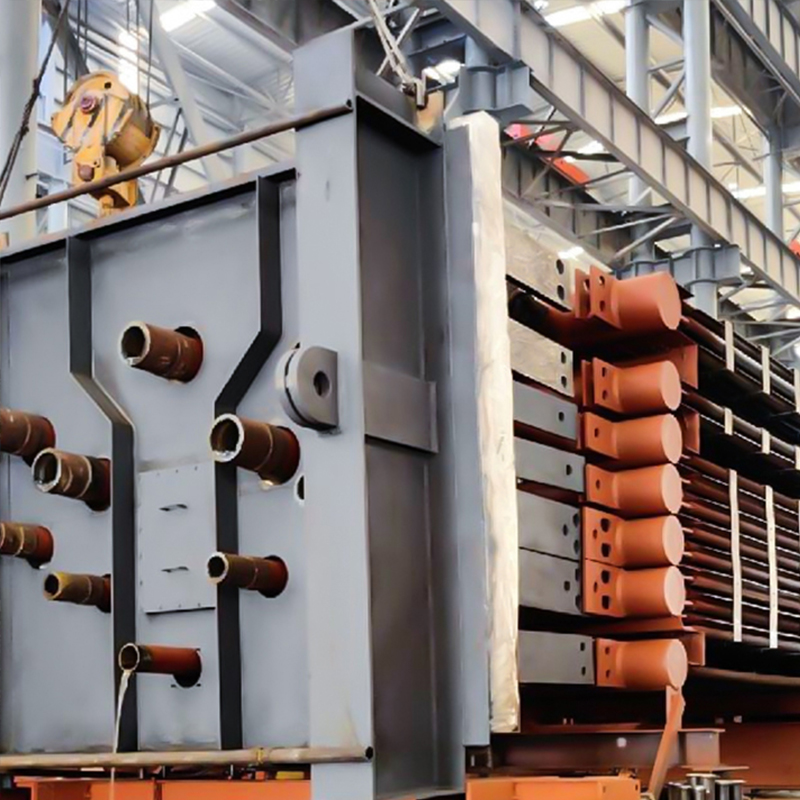 Industrial Waste Heat BoilerFlue gas volume |320,000 Nm³/h| | Inlet flue gas temperature |450°C| | Outlet flue gas temperature |100°C| | Steam evaporation rate |3.8-54.5 t/h| | Steam pressure |0....View Product →
When the gas stream is dusty or the duty swings hard between load points, the choice between extended and bare surface deserves a second look. The comparison between H-type finned tubes and smooth tubes usually comes down to how the gas stream behaves across a full maintenance cycle rather than how it looks at commissioning.
Extended surface wins when
- The gas stream is clean or lightly dusted
- Plot space is constrained and the bundle must stay compact
- The gas-side film coefficient is the limiting resistance
Bare tube holds up better when
- The gas carries sticky ash that bridges fin gaps
- Soot blower access is limited
- Radiation rather than convection sets the duty
Fin geometry is a maintenance decision disguised as a thermal decision. A bundle that gains 30 percent more surface but loses half of it to ash bridging within one season is a net loss.
The Numbers That Decide Whether It Pays Back
On boilers with flue gas exit temperatures above 150 degrees Celsius, an economizer retrofit usually pays back inside two years. Below that threshold the case depends on fuel price, annual operating hours, and how much margin sits between metal temperature and the acid dew point.
About 1 point Thermal efficiency gained per 20 degrees Celsius cut in flue gas exit temperature
Up to 8x External surface area of an H-type finned tube against a bare tube of the same length
150 to 250 Degrees Celsius, the flue gas window where low-temperature economizers typically operate
Surface area is the lever, so it is worth seeing how the common tube geometries compare at equal bundle length.
Every gigajoule recovered on the gas side is roughly one gigajoule of fuel the process no longer has to burn, provided that heat is actually delivered to the feedwater or process stream instead of being dumped through a bypass.
Selection Checklist Before You Commit
Size the surface from the heat balance first, then let the fin geometry follow the gas conditions. Reversing that order is the single most common source of underperforming waste heat recovery projects.
- Lock down the gas conditions: mass flow, inlet and outlet temperature, dust loading, moisture content and dew point.
- Work backward from the heat balance. Fix the duty first, then let geometry follow. Never pick a surface area and hope the duty appears.
- Match the fin form to the stream. Use H-type fins where ash bridging is the main risk, and spiral fins on clean streams where maximum surface is the goal.
- Let the dew point pick the material. Low-temperature tube selection should follow the acid dew point, not the catalogue price.
- Verify the manufacturing base before fabrication starts, including welding procedures, radiographic coverage and pressure part compliance paperwork.
- Reserve room for soot blowing and tube withdrawal. A bundle that cannot be pulled out will eventually be cut out.
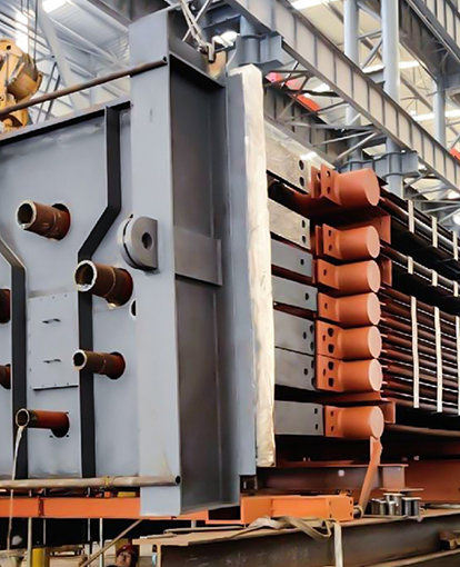
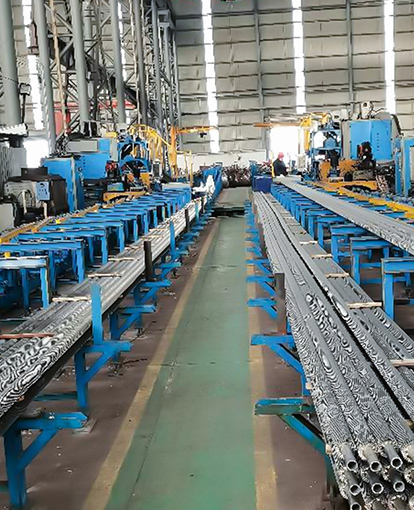
Manufacturing depth matters more here than in most equipment categories. Wuxi Jinker Power Equipment publishes its welding line count, radiographic inspection setup and certification scope, which gives a buyer something concrete to check a request for quotation against.
A selection that ignores turndown is a selection that only works in the commissioning report. Ask what the system does at 40 percent load before signing anything.
Fouling, Corrosion and the Cost of Standing Still
Fouling resistance can exceed three times its design value within a few months of service, and it leaves almost no obvious trace. Steam temperature still reads normal while the flue gas exit temperature has already climbed 15 to 20 degrees.
- Ash bridging, which blocks fin passages and silently removes effective surface area
- Acid dew point corrosion, where tube wall temperature drops below the sulfuric acid condensation threshold
- Erosion, where dust-laden gas wears fin edges and eventually the tube itself
- Thermal fatigue, where cycling creates differential expansion between tubes and tube sheets
Three trends catch all four failure modes earlier than any plant walkdown: flue gas exit temperature, gas-side pressure drop, and feedwater flow. Tracked together, they tell you whether the transfer surface is degrading or the operating point has simply shifted.
A 20 degree rise in flue gas exit temperature on a boiler that previously ran at 150 degrees usually means the economizer has already lost a meaningful share of its effective transfer area.
Frequently Asked Questions
Is a heat transfer system the same thing as a heat exchanger?
No. A heat exchanger is a single device. A heat transfer system includes that device plus its flow paths, supports, instrumentation and the process environment it operates in. An economizer tested on a bench is one thing. The same economizer sitting in an erosive flue gas stream with a soot blower upstream is a different engineering problem.
How much fuel does an economizer actually save?
As a working estimate, every 20 degrees Celsius cut in flue gas exit temperature lifts overall thermal efficiency by roughly one percentage point, which translates into a fuel saving of about one percent. Real numbers depend on fuel type, gas flow, excess air and where the recovered heat ends up.
When should H-type finned tubes be chosen over spiral finned tubes?
Choose H-type fins when the gas carries dust and ash that would otherwise clog narrow fin gaps, because the wider channels resist bridging and clean more effectively under soot blowing. Choose spiral fins on clean gas where maximum surface per unit length is the priority.
When is adding an economizer a bad idea?
When the tube wall temperature would fall below the acid dew point and no bypass, feedwater temperature control or corrosion-resistant material can manage it. In that situation condensation and corrosion will destroy the tubes before the recovered heat has paid back the installation.
The reliable rule across all of these decisions is the same one that governs the whole system: define the operating envelope first, and let every component choice follow from it.