English
 Français
 Español



Content
A refinery turnaround leaves six weeks of downtime, a 2.4 m duct opening, and a flue gas stream entering at 340 C that has to leave at 155 C. A catalogue shell-and-tube unit built around standard diameters and tube lengths will either oversize the bundle or push the gas-side pressure drop past what the induced draft fan can pay for. That gap between a datasheet and a real duct is where custom heat exchangers are specified.
This guide covers what actually drives a custom heat exchanger design for industrial heat recovery: the duty envelope, the tube and fin geometry, the material and code decisions, and the checks a buyer should run before releasing a purchase order.
What Makes a Heat Exchanger Custom
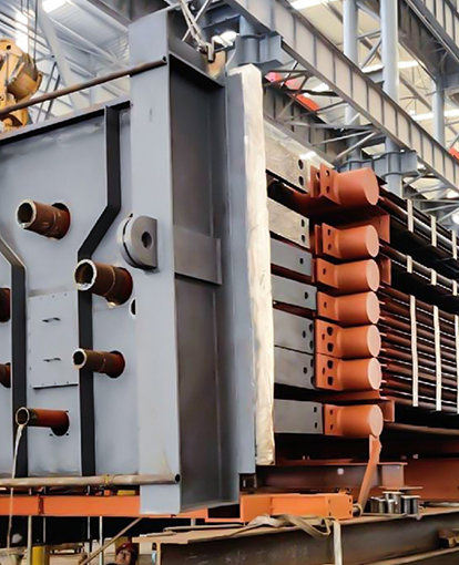
A custom heat exchanger is engineered around a duty envelope rather than selected from a fixed size range. The envelope fixes mass flow, inlet and outlet temperatures, allowable pressure drop, fouling behaviour and the space the unit has to fit into. Tube diameter, fin type, fin pitch, material and header layout all follow from those numbers.
A custom heat exchanger is a thermal unit whose surface area, geometry and materials are calculated for one specific gas or liquid stream and one specific installation envelope, instead of being chosen from a catalogue of standard sizes.
The difference shows up in three places. Surface area is matched to the duty instead of rounded up to the next standard bundle. Gas-side pressure drop is treated as a hard constraint rather than a by-product of selection. And the tube layout is built around the duct opening you actually have, including the lifting route into position.
Catalogue unit
- Sized to a standard shell diameter and tube length
- Pressure drop follows from the selection
- Fouling allowance fixed by the standard design
- Delivered from a fixed product range
Custom unit
- Surface area calculated from the heat duty
- Pressure drop held inside the fan curve
- Fin pitch and cleaning access set by the dust load
- Built to the envelope, weight and lifting limits
Six Inputs That Drive the Design
Six inputs decide roughly 80 percent of a custom heat exchanger design: mass flow, inlet temperature, the outlet temperature target, allowable gas-side pressure drop, dust or fouling load, and the installation envelope. Everything else in the quotation is a consequence of those six numbers.
| Input | Typical range | What it changes |
| Gas mass flow | 5 to 200 t/h | Tube count, face area and gas velocity |
| Inlet temperature | 180 to 600 C | Material grade and expansion allowance |
| Outlet temperature target | 120 to 200 C | Balance between heat recovery and dew point margin |
| Gas-side pressure drop | 200 to 1200 Pa | Fin pitch, number of rows and face velocity |
| Dust or fouling load | low to 300 g/Nm3 | Fin type, fin pitch and cleaning access |
| Installation envelope | duct or opening size | Module dimensions and lifting route |
Leave one of them out and the quotation comes back either oversized or optimistic. The outlet temperature is the usual trap. Cooling flue gas below the acid dew point of sulphur-bearing fuel turns a heat recovery project into a corrosion project within a couple of seasons.
Rule of thumb: every 20 C reduction in stack temperature recovers roughly 1 percent of boiler fuel input, but only down to the acid dew point of the fuel you actually burn.
Finned Tubes Set the Thermal Budget
On the gas side, the finned tube carries the thermal budget. A well-chosen finned tube multiplies the external surface area by roughly 3 to 6 times that of a bare tube of the same diameter, which is what makes it practical to recover heat from a large, low-pressure flue gas stream.
- H-type finned tube. Rectangular fins are welded in pairs along the tube, leaving wide gas lanes that resist ash bridging and clean easily with sootblowers. It is the usual choice in dusty service or with solid fuels.
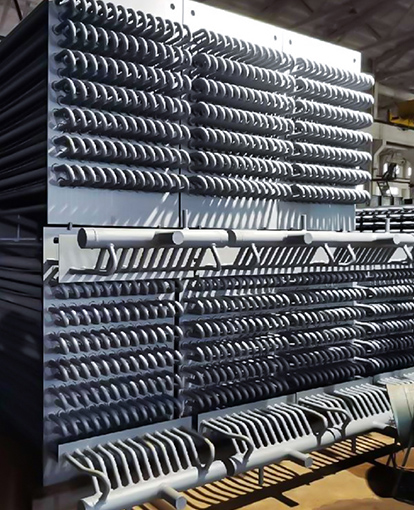
- Spiral finned tube. A continuous strip is wound and welded around the tube, giving the highest surface area per metre and the tightest practical pitch. It performs best in cleaner gas where bridging is not a risk.
- Heat pipe. A sealed, evacuated tube moves heat isothermally between two streams with no cross-contamination, which matters when a leak between flue gas and product is unacceptable.
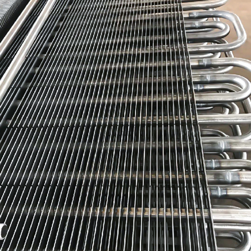 H-Type Finned Tube for Boiler and Heat Exchanger ApplicationsH-shaped finned tube with high-frequency welded fins, suited to dust-laden flue gas and low-resistance heat transfer in boilers and industrial heat exchangers.View Product →
3 to 6 x external surface area versus a bare tube
2 to 6 mm typical fin pitch in boiler service
10 to 20 mm typical fin height on economizer tubes
Fin pitch is a compromise. Tighter pitch packs more surface into the same box but raises the risk of ash bridging and increases cleaning frequency, so dusty service usually rewards a slightly wider pitch.
Economizers Recover Heat at the Tail End
A boiler tail flue gas economizer is usually the cheapest place to add heat recovery, because the gas leaving the boiler still holds useful heat at a temperature where a compact, low-cost unit can do the work.
Feedwater typically enters at around 105 C and leaves at 130 to 150 C, and that heat comes out of the gas stream rather than out of extra fuel. The same principle covers three common duties:
- Boiler tail flue gas, where the exhaust is comparatively clean and the main constraint is the acid dew point.
- Industrial kiln flue gas, where dust and alkali content drive the fin pitch and often the tube material.
- Process equipment flue gas, where composition shifts with the batch and the unit has to stay stable across swings.
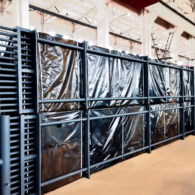 Boiler Tail Flue Gas Economizer for Feedwater HeatingRecovers heat from boiler exhaust to raise feedwater temperature and reduce fuel use, with serpentine or spiral finned tube construction.View Product →
An economizer does not need exotic materials to pay back. It needs the right fin pitch, a tube grade that survives the dew point, and a pressure drop the existing fan can absorb without a motor change.
Waste Heat Boilers and HRSG Systems
When recovered heat is needed as steam rather than as sensible heat, the custom unit becomes a waste heat boiler or a heat recovery steam generator sized to the exhaust stream instead of to a fuel input. Design starts on the gas side: flow, temperature and composition fix the evaporator surface, drum pressure and steam output.
Industrial waste heat boilers recover steam from kilns and process lines. Power station units sit behind gas turbines in combined cycle plants. Waste treatment boilers handle flue gas from incineration, where corrosion and fouling shape the layout more than the heat duty does.
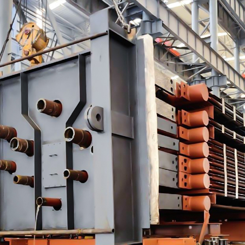 Industrial Waste Heat Boiler for Steam RecoveryProduces steam from flue gas in steel, chemical, cement, and smelting operations, with designs adapted to dust, corrosive gases, and varying temperatures.View Product →
One number settles most HRSG sizing arguments: the pinch point. A tighter pinch recovers more heat, but it buys that heat with more surface area and a larger gas-side pressure drop.
Materials, Codes and Weld Quality
Material selection follows metal temperature and gas chemistry, not design pressure alone. The bands below cover most flue gas and process gas duties.
| Material | Practical metal temperature | Typical service |
| Carbon steel | up to about 425 C | Clean, dry flue gas; lowest cost option |
| 1.25Cr-0.5Mo | 425 to 540 C | Hotter gas paths with moderate creep demand |
| 2.25Cr-1Mo | 540 to 580 C | High temperature HRSG and process service |
| Austenitic stainless steel | up to 600 C and above | Moist or mildly corrosive gas, better dew point resistance |
| Duplex and higher alloys | duty specific | Chloride-bearing or acidic condensate conditions |
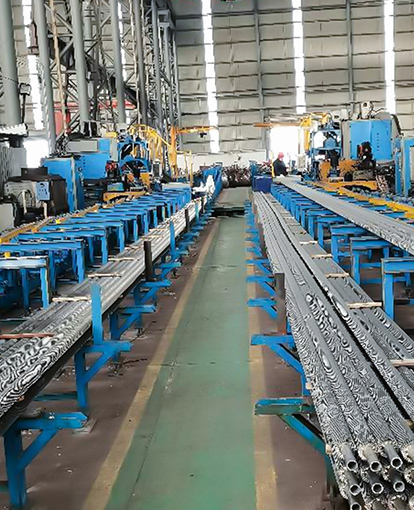
Fabrication matters as much as the tube grade. Pressure parts are built to recognised boiler or pressure vessel codes, welding is qualified and documented, and weld quality is verified by radiography or real-time imaging rather than visual inspection alone. Buyers working through that review can use this ASME pressure part compliance guide for engineers as a checklist.
Ask for the tube material, the fin material and the welding consumable to be listed separately on the drawing. They are often different grades, and treating them as one item is one of the most common causes of early tube failure in flue gas service.
How to Vet a Custom Heat Exchanger Supplier
Ask for the thermal calculation, the pressure drop curve and the welding procedure before you ask for the price. Those three documents separate a manufacturer that can carry a project from one that can only quote one.
Read the duty data sheet
Flow, temperatures, gas composition, dust load, design pressure and site conditions should fit on one page. If the supplier does not request all of them, the thermal design is a guess.
Check the thermal and hydraulic output
Surface area, face velocity, fin pitch and predicted gas-side pressure drop at design and at 110 percent load. A design that only works at the design point will not survive a cold start.
Confirm materials and the corrosion case
Minimum metal temperature against the acid dew point, corrosion allowance, and the cleaning method the tube layout actually allows.
Review fabrication and inspection
Welding procedure, NDT method, hydro test pressure and inspection release points. Verified certified pressure part fabrication capacity and in-house radiographic inspection shorten the approval path considerably.
Match the schedule to the plant
Module dimensions, lifting weight, site assembly scope and delivery milestones against the outage window.
A supplier that can show a heat balance, a pressure drop curve and a weld inspection plan on the first technical pass carries a very different risk profile from one that only sends a price.
Frequently Asked Questions
What is a custom heat exchanger?
It is a thermal unit whose surface area, geometry and materials are calculated for one specific stream and one installation envelope. It is designed for the duty rather than selected from a standard size range.
When is a custom unit cheaper than a standard one?
When your pressure drop, dust load, gas chemistry or available space falls outside a standard unit range. The unit price is usually higher, but fan power, cleaning downtime and service life normally swing the total cost the other way.
What belongs in a request for quotation?
Mass flow, inlet and outlet temperature, gas composition including sulphur and moisture, dust loading, allowable pressure drop, design pressure and temperature, corrosion allowance, and the installation envelope with lifting constraints.
Get the duty envelope right and the rest of a custom heat exchanger quotation becomes comparable between suppliers. Skip it, and you are comparing three different assumptions.